Eng-Tips is the largest engineering community on the Internet

Intelligent Work Forums for Engineering Professionals

  • Congratulations waross on being selected by the Tek-Tips community for having the most helpful posts in the forums last week. Way to Go!

Fastener Pattern Force Hand Calc vs FEM 2

Status
Not open for further replies.

Lee.Conti

Automotive
Nov 8, 2019
87
0
0
SG
Hi All,

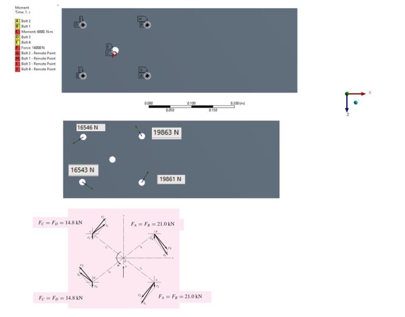
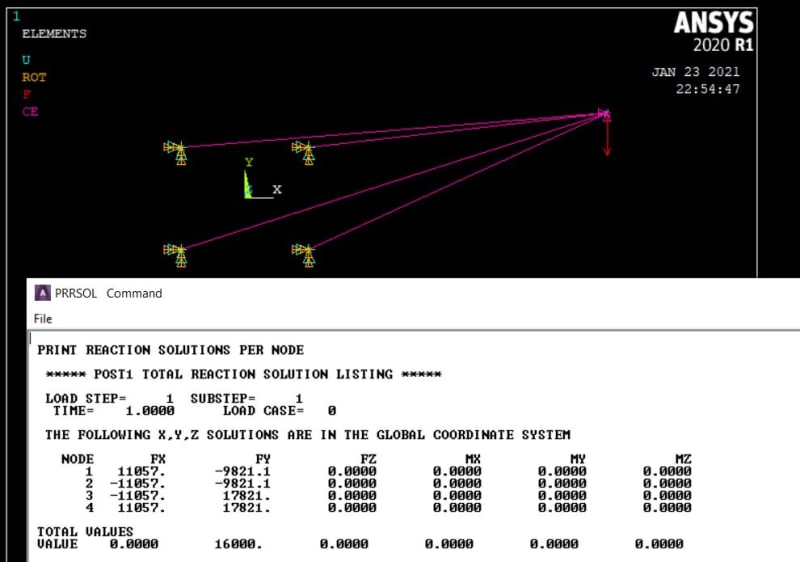
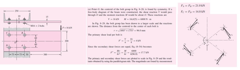
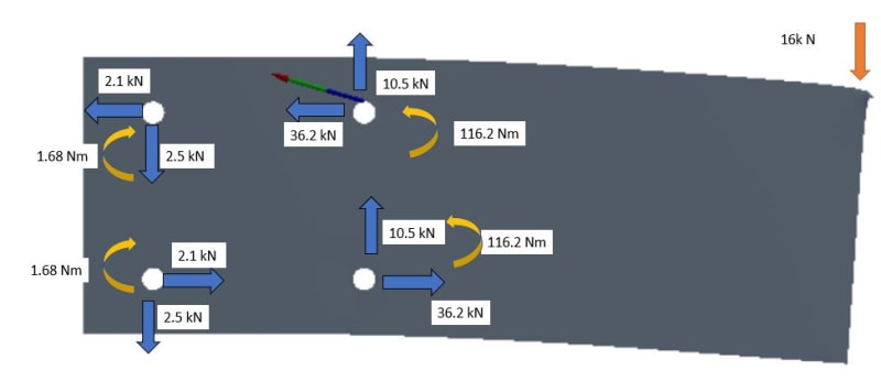
I am trying to compare using FEA results to calculate the bolt forces with the hand calculation from Shigley example... but I can't match it... I extract the forces and also moment... but I am not sure if the FEA results are correct although summation of forces are matching to applied force...

Anyone can tell what I miss out in the FEA?
shig_b0qyfn.jpg


ansys2_kqnyxw.jpg
 
Replies continue below

Recommended for you

are you fixing the fasteners for moments ? fasteners should take only shear.

A Major problem you have is that you don't have force equilibrium ... 16 down applied, 20.5 up reacted ???

another day in paradise, or is paradise one day closer ?
 
No, I mean the little curved arrows at each fastener. The fasteners should not react moments, only shear forces.

But why don't you have a total reaction of 16 kN ?

another day in paradise, or is paradise one day closer ?
 
Hi rb1957, I realized a mistake in the FEA results. I upload picture again. The total reaction force is around 16kN.

The bolts near to applied load take up most of the forces...

I re-run the ansys with free the moment at constraints, the reaction forces remain the same... comparing to hand calculation or joint fitting calculation, we transfer the force to the centroid of fitting and distribute forces evenly as well as induce moment...but FEA gives the reaction forces very much different...
 
The classical solution assumes the plate is rigid. However, from your FEM, you can see it is not deforming in a rigid manner. Are you using a realistic value for the spring constants for the fasteners? This should "soften" the reaction from the fasteners and the plate may deform more rigid-like. If you just grounded the nodes at the fastener locations, that connection may be too "hard" as compared to the classical assumption.

Brian
 
Thanks ESPcomposites, I am using RBE2 with a node at the center of the hole. I run two type of constrains with all DOF fixed and translational fixed only but reaction forces are about the same...

hole_sfuuik.jpg
 
Always start simple. Go for a 2d mesh instead of 3d with fastener holes etc, once you can correlate the 2d model to the hand calc, then go 3d if you really need that level of detail.
Regardless, use a cbush between the mesh and the spc'd node to represent the fastener/joint shear stiffness, and set the stiffness a few orders of magnitude below that of the plate. If everything else is modelled correctly you should see a reasonable correlation between the hand calc and fem.
Ansys is horrid in my opinion, though it has its place.. Try using nastran if you can, and get used to manipulating the deck by hand: that way you have certainty over the solver inputs, unlike in a GUI preprocessor.

 
Hi Ng2020, it is a very simple example... 3D not gonna make much different as above.

I shifted the applied force at the centroid of bolts with moment force manually, I can get the reaction forces pretty close to hand calculation...

Does it mean that it does not transfer the moment to the centroid of Bolts in FEA? I understand that usually the bolts near to the applied force will take up more loads...

pic1_qis3ao.jpg
 
As someone mentioned earlier, the discrepancy between the hand calc and FEM is likely due to the relative flexibility of the plate compared to the bolt shear flexibilities.
The hand calc assumes the plate to be rigid, and the bolts are assumed flexible. Whereas in your FEM the plate has a finite stiffness, and from the way you've modelled it, it sounds like the bolts are rigid (mesh->rbe->grounded node).

Statically indeterminate problems are all about stiffness - add some flexibility to the fastener (use a bush between the the and ground).
 
Thanks for your reminder... that is right... it is considered rigid in classical calculation unless I use RBE in FEA to distribute the forces...

Thanks!
 
Maybe I did not say it clearly... I now catch what ESP and you said that in my model, it is not rigid in the first model but in our calculation, we assume it is rigid for force/ moments transferring...

Now I re-run the FEA using RBE3... I can get the same results as hand calculation...


rbe1_hgdnbh.jpg
 
When you hard grounded the two fasteners on the right side, most of the reaction was going to them. You could see this from the deformation and reaction forces so I suspected that is what you did. In reality, the fastener connection has flexibility. Once you add account for that, you get a different result. This is because you have an indeterminate system, which is a function of the stiffness of the entire system.

Brian
 
If I run a bracket in FEA, I constrain four fasteners in all 6 DOF... can I take the reaction forces and moments for bolt assessment?

bracket_dzf24w.jpg
 
1) do not model the fastener holes.
2) do not model that bracket with solid elements.
3) connect the bracket nodes at fasteners to ground or adjacent parts with spring or bar or fastener elements with appropriate fastener stiffnesses.
4) use the spring/etc element results to get fastener loads
 
don't constrain all 6 dof ... that is (IMHO) being lazy. It is better to constraint 3 (forces) only. It is best to give these 3 dof finite stiffness as opposed to the finite stiffness of a hard constraint.

consider modelling the problem in the same way as you are solving it. constraint 6 dof at the centroid of the fastener pattern, then read the fastener forces at the fastener nodes.

another day in paradise, or is paradise one day closer ?
 
Yes, you should place an element(s) that connect the plate to ground. These element(s) could be springs, a beam, CBUSH, other. Spring elements or a CBUSH will allow you to directly input the spring constant while you would have to "back out" the effective spring constant if you use a beam element. I suspect that a small spring stiffness should give you the result you want (something like 100lb/in or 1000lb/in), but you should use a realistic value as for another check. If you keep increasing the spring stiffness, you will reach a result similar to the one where you grounded the holes originally (aside from the moments that were reacted - but I don't think that will matter too much based on the geometry). While you shouldn't constrain the fasteners to react a moment, its a pretty soft load path and won't pick up much even if you do.

Brian
 
I think you've answered your own question.

when you run the model with the load at the centroid, as per the hand calc, you get equivalent answers.

when you run the FEM with the load applied as per the real world, you get different answers.

the hand calc assumes an infinitely rigid beam, for all intents and purposes cantilevered at the centroid of the bolt group. But your beam is not rigid ... it'd be "interesting to see what happens with a beam 100 (1000?)x stiffer, 100 (1000?)x softer. My guess is you'll see the vertical reaction approach a SS beam, and the lateral reactions would be a localised couple.

If you assume a SS beam, then the RH bolts react 16*500/150 = 53.3kN, 26.7kN per ... slightly more conservative than the bolt group.

another day in paradise, or is paradise one day closer ?
 
Status
Not open for further replies.
Back
Top