Eng-Tips is the largest engineering community on the Internet

Intelligent Work Forums for Engineering Professionals

Fastener RBE Post-Processing Issue. Solid averaging. 2

Status
Not open for further replies.

ecFem

New member
May 19, 2023
19
0
0
FR
Helllo all,

I'll post two different questions in a same thread.

-----------------------------------------------------------------------------

Question 1

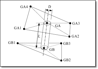
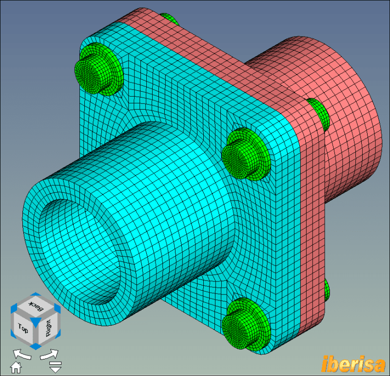
I have made several fastener connections in a model, through spider RBE3s and the fastener represented by a RBE2. I leave an image so you can see.

Image_xc7im5.png


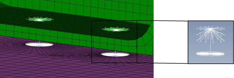
The problem is that when I try to extract the loads acting on the element, it's zero in both nodes of the RBE2. I realized that it's because the contribution of both RBEs is cancelled, which is logical. I've tried lots of things to extract these forces but I couldn't do it.
Any experienced FEMAP user could provide a workaround ? Otherwise I'll have to change the RBE2 for CBEAM or CBUSH, but that's something I am trying to avoid because it will be a ton of work.
However, lesson learnt, I won't use RBE3 spider + RBE2 if I want to extract loads.

-----------------------------------------------------------------------------

Question 2

I was performing some post-processing in solid elements, around a hole to be more precise. I had an issue with a high local stress.
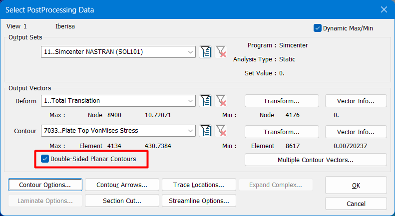
A more experienced colleague told me that I was using "Average" for the result output and that I should use (it is what he does) "No average, Centroid Only".
By doing this the stress shown in the solid element passed from 600 [MPa] to around 240 [MPa].
Next, I did the same with plate elements, but the stress (MaxPpal) increased.

My question, therefore, is : How does it work with plate and solid elements ? I mean it seems counterintuitive that by no averaging the results, the output is higher.


Thanks in advance for your time and sharing some knowledge !

Cordially,
EC
 
Replies continue below

Recommended for you

This has been discussed previously in various FEA forums on this site. Sigh. ALL of the stresses around the hole that is connected to an RBE2 or RME3 wagon wheel thing are RUBBISH, ie, wrong. This type of modelling is more or less ok for getting the fastener loads, but does not represent the fastener contact loading on the joint members correctly.

You should be able to get grid point forces at the nodes connecting the RBE3 and RBE2 elements. But replacing the RBE2s with beam elements will be much more representative of the joint stiffness. Or connect the RBE3s and RBE2s with spring elements connecting coincident nodes at each end. Look up the Ruttman modelling method online or on one of the forums here.
 
Sea EC,
As SWComposites says, how to define bolt connections this is the ethernal question, always the same problem.
The API on CUSTOM TOOLS > MESHING > HOLE-TO-HOLE FASTERNER do the job using a CBEAM element with the bolt cross section and a spider rigid RBE2 with rotational DOF OFF for head & nut, not need to "invent" exotic methods involving RBE3 elements. The above API is the classical method we ran in FEMAP & NASTRAN since years, but in some industries is not used like AeroSpace or Airplanes, instead they use internal methods based in a mix of elements like Springs & CBUSH with parameters & coefficients that only they know with internal data.

But please note we have in FEMAP & NASTRAN a method that not many people use or is aware of it (I have just mentioned today in the SIEMENS FEMAP FORUM): the CWELD element connector!!.
In fact, I use it a lot, is very simple but extremely effcient & accurate, not need to create pad & washers, you can ignore the hole.
Take a look to my blog: (I note the post was written in year 2012!!)
In fact, the CWELD is basically a CBEAM element, with useful features:
cweld_format_crnmvo.png


My favorite method is PATCH-to-PATCH: you don't need congruent mesh!!.
cweld_tipos_conectividades_pz8qhn.png


And you have the grea API from FEMAP team: CUSTOM TOOLS > MESHING > WELD-FASTENER ELEMENT GENERATOR: fort the bolt location you can create an EXCEL file with X,Y,Z + BOLT DIAMETER, or a DATA SURFACE internal in FEMAP, and automatically FEMAP will do the job!!

CWELD-FASTENER-API_bdw7yq.png


This is a picture of a FEMAP model of a bolted flange I am running just now.
According the NASTRAN manual:
"The CWELD element let you establish connections between points, elements, patches, or any of their combinations. Although there are a number of different ways to model structural connections and fasteners in Simcenter Nastran, such as with CBUSH or CBAR elements or RBE2s, CWELDS are generally easy to generate, less error-prone, and always satisfy the condition of rigid body invariance".

cweld-application-example_jisjz2.png


You can list CWELD forces using LIST > OUTPUT > FORMATTED, then you can check if the CWELD pass or not any bolt checks according to AISC (ASD) 9th edition, for instance, OK?. Enjoy!!

Code:
Format  : NASTRAN CWELD Forces
Output Set 11 - Simcenter NASTRAN (SOL101)
                                F O R C E S   I N   W E L D   E L E M E N T S   ( C W E L D )

    ELEMENT          BEND-MOMENT END-A            BEND-MOMENT END-B               - SHEAR -               AXIAL
      ID         PLANE 1 (MZ)  PLANE 2 (MY)   PLANE 1 (MZ)  PLANE 2 (MY)   PLANE 1 (FY)  PLANE 2 (FZ)    FORCE FX       TORQUE MX
      10395      2.749540E+4   6.981934E+3    7.995509E+3   7.786929E+4    1.559992E+3  -5.670988E+3    6.351530E+3    6.393677E+2
      10396      4.663103E+4  -1.684140E+5    1.078687E+4   1.218087E+5    2.867533E+3  -2.321782E+4    1.031769E+4    1.222788E+3
      10397     -4.663353E+4  -1.684278E+5   -1.078458E+4   1.218263E+5   -2.867916E+3  -2.322033E+4    1.031783E+4   -1.221535E+3

Best regards,
Blas.

By the way, in my blog I explain the differences between RBE2 & RBE3 rigid elements, try if you like:


~~~~~~~~~~~~~~~~~~~~~~
Blas Molero Hidalgo
Ingeniero Industrial
Director

IBERISA
48004 BILBAO (SPAIN)
WEB: Blog de FEMAP & NX Nastran:
 
Ah!, regarding postprocessing stress results:
• Nodal stress in solid elements: if the mesh density is correct (not coarse or highly distorted) the nodal stress is a correct result. But please have in mind: if the node location is singular, not matter you refine your mesh the nodal stress will be higher and higher. In this case to demostrate that the stress result is convergent (mesh undependent) use another location at a near distance of the singular point.
• Nodal stress in shell/Plate elements: well, here I always use the following options.
- Contour type: elemental. Yes, because if you have a node that is shared by two shell elements of different thickness or material you can understand that is not correct to "average" nodal stresses, is not correct. This is the reason why in some cases nodal streses in shell/plate elements are smaller than centroidal elemental stresses.

By the way, to get centroidal-only elemental stress you need to set ON the option "ELEMENT CONTOUR DISCONTINUITIES = NO AVERAGING", and set OFF the option "USE CORNER DATA".
In my case with CONTOUR TYPE = ELEMENTAL I set SMART AVERAGING because I use "elemental Contour Discontinuities" is not activated, excepts for the options property, material or angle above 20º, OK?.

contour-options-plate-stress_qsnsf2.png

contour-options-plate-stress-double_wbymrl.png


Best regards,
Blas.

~~~~~~~~~~~~~~~~~~~~~~
Blas Molero Hidalgo
Ingeniero Industrial
Director

IBERISA
48004 BILBAO (SPAIN)
WEB: Blog de FEMAP & NX Nastran:
 
Blas - great post, and thanks for reminding me about the CWELD elements (I stopped doing much FEA work around the time those elements were released, as I had by that time greatly exceeded my lifetime quota of FEA headaches); I agree those are the way to go for Nastran modelling of fasteners for joints with two joint members to get fastener force distributions. However for joints with 3 or more joint members then fastener bending continuity needs to be maintained thru the joint thickness, so the Ruttman type approach must be used.

But the plate stresses in the vicinity of the CWELD elements is not accurate. One has to extract the fastener forces and then do a local hole analysis separately from the FEM.
 
Dear SWCOMPOSITES,
I forgot to mention the limitations of the CWELD NASTRAN connector:
BOLT PRELOAD: yes, this is an important limitation. In reality, all bolting joints are preloaded, then you can imagine. But the CWELD connector is of inmediate application, easy to mesh, fast, thanks to the FEMAP API, and more accurate than the cbeam + rbe2 spider elements, not comparisson.
In any case, if you want accuracy + bolt preload you always can study the joint using solid elements, visit my blog:

caf-consulting-bolt-preload1_x4wqzm.png


bolt-preload-mesh_mfxogx.png


• Connecting more than 3-layers of elements: The patch-to-patch connection can also be used to connect more than two layers of shell elements. For example, if three layers need to be connected, a second CWELD element is defined that refers to the same spot weld grid GS as the first CWELD. Patch B of the first CWELD is repeated as patch A in the second CWELD.
• CWELD elements are not supported in material or geometric nonlinear analyses.
• Limitations in area:
[ul]
[li]Patch-to-patch connections are recommended when the cross sectional area of the connector is larger than 20% of the characteristic element face area.[/li]
[li]The patch-to-patch connection is sufficiently accurate if the ratio of the cross sectional area to the surface patch area is between 10% and 100%.[/li]
[/ul]

Best regards,
Blas.

~~~~~~~~~~~~~~~~~~~~~~
Blas Molero Hidalgo
Ingeniero Industrial
Director

IBERISA
48004 BILBAO (SPAIN)
WEB: Blog de FEMAP & NX Nastran:
 
Thank you very much SW and Blas for your time and awesome answers !

I've read many of your articles in your blog Blas, they are magnificent. And as a Spanish speaker most of them are even easier to understand.
 
Status
Not open for further replies.
Back
Top