Eng-Tips is the largest engineering community on the Internet

Intelligent Work Forums for Engineering Professionals

  • Congratulations waross on being selected by the Tek-Tips community for having the most helpful posts in the forums last week. Way to Go!

Fastener selection 2

Status
Not open for further replies.

Meherrahul

Aerospace
Apr 1, 2021
12
0
0
IN
Hello everyone,

I have few questions regarding HI-LOK fasteners used in aerospace industry.

If you look at the attached fastener's table, you will find the last two columns under the heading "DOUBLE SHEAR NEWTON MINIMUM" and "TENSION NEWTON MINIMUM". Can anyone please explain on what these terms mean ? Any suggestion would be greatly appreciated.

I think the TENSION NEWTON MINIMUM means the minimum pretension in the fastener as it's collar wrenching device breaks off when the desired torque is reached. But, I also suspect that these may be allowable tensile load on fastener.

 
 https://files.engineering.com/getfile.aspx?folder=2f35d9ea-2d2d-480b-b549-e630721ea204&file=HLM48
Replies continue below

Recommended for you

these are the allowable loads in tension or double shear (nothing to do with the installation torque, shearing the collar).

So the single shear allowable load is 1/2 the double shear. Beware though, these are the fully effective values, and the allowable load (in shear) can be reduced by bearing allowable of the sheet (like for thin sheets).

another day in paradise, or is paradise one day closer ?
 
Also...
HLM48 is a METRIC Hi-Lok pin.
All dimension are decimal-millimeters... and double-shear and tension design ultimate loads are expressed in 'Newtons'.

A similar-to is the HL48, which is a US-standard HL pin.
All dimensions are in decimal-inches... and the double-shear and tension design ultimate loads are expressed in #-F [pounds-force].


Regards, Wil Taylor
o Trust - But Verify!
o We believe to be true what we prefer to be true. [Unknown]
o For those who believe, no proof is required; for those who cannot believe, no proof is possible. [variation,Stuart Chase]
o Unfortunately, in science what You 'believe' is irrelevant. ["Orion", Homebuiltairplanes.com forum]
 
Thank you rb1957 and WKTaylor for your quick answers.

Then, How to get the pretension on the fastener to assess whether the mated parts are safe or not ? The pretension value should be mentioned in the table. But I can't find it in the table or anywhere else ?
 
"pretension" or preload is usually defined by the application, high tension loads usually have high pre-loads. If you have to define a preload (because of your loading, and you don't want the joint to gap) then you shouldn't be using Hi-Loks/Hi-Lites.

Yes, Hi-Loks/Hi-Lites have some pre-tension but is is usually a small enough value that it doesn't get into the calcs.
I remember seeing something from the manufacturer about pre-loads, but I've lost it.
Obviously, pre-load is higher for tension nuts.

The impact of pre-tension is felt only local to the part. It would be a problem if the joint plates (the "mated parts" as you say) could be easily crushed (like composite panel). Shouldn't be a problem for any typical metal.

another day in paradise, or is paradise one day closer ?
 
Ref Your HLM48 data sheet. In the upper right corner, illustration of installed fastener ASSEMBLY, there is a notation for recommended HL collars, thus...

REMAINING PORTION OF HI-LOK™
COLLAR AFTER ASSEMBLY

TYPICAL COLLARS:
HLM75, HLM78, HLM86


Smoothly/gently install any of the HL collars specified to produce a tension pre-load as-determined by the collar wrenching device... it is designed to shear-off/away in a narrow torque-range [NO torque-wrench required]. NOTE: abusive/abrupt torque-turn installations of HL collars will cause irregular pre-load installations. SMOOTH torque-turn to break-off is required... and beware... when collar-drives break, wrenches tend to 'jump-away' and bang-into other parts... bad practices will result in unintended damage. Take my words, mechanics have to be careful with large HL collars that have high break-torques… so they control how/where the wrench jumps/recoils-to, very suddenly. Even the mechanic can get hurt!

Go to the collar specs for more information. Based on material type and collar-threaded length... aluminum, steel/CRES/Titanium, etc.. and thread length: low=shear, higher=tension... the collar break-off torques will vary.

AND.. notice this statement below the assembly illustration...

SEE COLLAR STANDARDS
FOR COLLAR STRENGTHS.
LOWER STRENGTH (PIN OR
COLLAR) DETERMINES
SYSTEM STRENGTH

BTW... wink-wink... an old Hi-Shear [original company] Hi-Lok engineer... explained why collar torques are relatively 'high' compared with/to similar conventional nuts. The HL Pin/collar system was originally intended to replace 'stump-pin' and 'pin-pull lock-bolts' that have swaged-on collars, in hand assembly/repair situations. There was an assumption that there would be a slight tension relaxation of the HL Pin/collar [threaded] joint after collar-hex break-off as parts settle-together... the extra-high preload accounted for this.

Regards, Wil Taylor
o Trust - But Verify!
o We believe to be true what we prefer to be true. [Unknown]
o For those who believe, no proof is required; for those who cannot believe, no proof is possible. [variation,Stuart Chase]
o Unfortunately, in science what You 'believe' is irrelevant. ["Orion", Homebuiltairplanes.com forum]
 
I tried to open your attachment but I was unable to do so.

However, I will say, it is odd to me that you have published data with only gives tension and double shear allowables for a Hi-Lok. I have rarely ever seen joint test data for Hi-Loks or bolts in double shear. For example, no Boeing SRMs I am familiar with chapters 51-40-07 or any Airbus SRMs chapter 51-70-13-001 provide this test data.

That being said, there is plenty of double-shear test data for rivets. Examination of that data will show you that in general, double shear values are not simply 2x the single shear value. In a simplified sense (ignoring any deformation of the fastener) that might be true for the shank shear strength (simply because there are two shear planes), but those are only the extreme envelopes of the transitional strength.

Keep in mind a double shear joint can have sheets of different thicknesses. I have seen several sources state, with reference to double-shear strength:
"The strength of a double lap joint is the lower of: 1. Twice the single shear allowable of thickness t1, or 2. the double shear allowable for thickness t2, determined as the lower value of the allowable bearing load of the joint material and the allowable shear load of the fasteners." However, again, I think this is an oversimplification.

For example, we can easily plot rivet test data:

3_h6up4q.jpg


Keep in mind this plot is for the accepted thickness range for this fastener (clearly any thinner and the sheet bearing will be critical, any thicker and the fasteners will be direct shear critical).

But it is plain to see - at low values of thickness the single and double shear values are virtually indistinguishable. This makes sense because with the thinner end of the spectrum, we are close to bearing critical, which is sheet dependent and doesn't really matter if there are two shear planes or not. As the thickness grows, the transitional strength curves diverge from the sheet bearing curve and the single and double shear values also diverge. But the double shear values are not necessarily 2x single shear.

I would be curious to see the values you have for double-shear strength. Do the numbers line up if you simply calculate 2*(pi*(r^2))*Fsu? If so, those "allowables" are not really telling you anything about the joint strength behavior other than the extreme of the envelope.

EDIT: Assuming the attachment was just the datasheet for the fastener... the column of double shear strengths are in fact simply the shank area multiplied by the given shear strength 655 N/mm, multiplied by 2. Whether you cut that in half or not, all it is telling you is the shear critical load. Do not rely on that value. Similarly for the tension number... it is not accounting for things like pull-through, etc.

Keep em' Flying
//Fight Corrosion!
 
Hello, I have some more questions.[bigsmile]

rb1957 mentioned that Hi-loks fasteners should not be used for high tension application. Then I wonder, Are there any fasteners which offers controlled preload (similar to Hi-loks) and are suitable for high-tension application ?
 
Maybe someone else is more familiar with this... but...

Joints designed for high-tension require fastening intended for long-duration tension durability/reliability... which is not the design intent for HL pins/collars. Anywhere You can install a HL pin/collar You should be able to install a high reliability [PTH or FTH] Bolt + high strength washer(s) + tension nut... W/a torque-wrench.

NOTE.
HL design intent discussion 'is a term paper' from a guy like me; or a stack of design manuals for an aircraft OEM.

Simply-stated, HL pins/collars are 'threaded-rivets' for mass assembly of [primarily] shear structure with variable tensile loads due to changing shear-loading... like the swaged-collar lockbolts they replaced.

AND because they are a 'threaded-rivet-system' instead of a 'swaged-rivet-system', the allowable diameter range... smallest to largest diameters... is dramatically greater: equivalent to most bolts/nuts [except for the more specialized purpose of shear, as discussed].


Regards, Wil Taylor
o Trust - But Verify!
o We believe to be true what we prefer to be true. [Unknown]
o For those who believe, no proof is required; for those who cannot believe, no proof is possible. [variation,Stuart Chase]
o Unfortunately, in science what You 'believe' is irrelevant. ["Orion", Homebuiltairplanes.com forum]
 
I don't know how much you know about fasteners, but (apologies) I'm guessing it is not much.

I'd start with basic texts, like Bruhn or Niu or Favbel (or many others).

Typically fasteners don't control preload. Preload is controlled by the torque application, like torque wrench, Pre-Load Indicating (PLI) washers, or "turn of nut".
HiLoks (and Hi-Lites) have collars that shear when a correct torque is applied, but are not typically used is high tension situations (even with tension nuts) as this troque is not very high, not like what a "proper" tension bolt would want to prevent gapping under load.

another day in paradise, or is paradise one day closer ?
 
OK, so first we need to understand what makes a fastener strong or weak in tension. Most commonly seen fasteners in airframes are not particularly good in tension because of the nature of their installation. Rivets and lockbolts (ie huckbolts) which have swaged collars, rely on deformation of the material to hold the system in place, which is inherently weak in tension. Hex drive bolts like Hi-Loks are somewhat better not great. Generally these are made in two varieties - shear head and tension head; however, tension head Hi-Loks are really just meant for situations where higher preload is required and they are installed with collars to match.

This is a really good site for basics:

One way that you can figure out good fasteners for tensile application is to look for existing designs which have a lot of tension in the load path and see what is installed. For example, beam end fittings and big lugs at wing roots, etc will undoubtedly have fasteners meant for high tension.

Generally speaking, in this type of scenario, we would not actually specify a Hi-Lok but instead would use a bolt with a removable collar whose torque is controlled measurement, and not through deformation or shear-off of the fastening system itself.

You might find this in industry referred to as externally wrenching bolts. These are generally designed specifically for shear, tension, or fatigue rating, etc. They come in all kinds of varieties, 12 pt, hex, pan, socket, etc. For Boeing, these would be something like BACB30NJ, BACB30LJ.

From TM 1-1500-204-23-6:
"External wrenching bolts (12 point), as shown in figure 2-6, are high-strength bolts used primarily in tension applications. They are furnished with either drilled or undrilled heads."


Otherwise something like NAS6620, NAS563, NAS572 and a plethora of others. Installation relies on specific torque values in tables or controlled by the spec (again for example, working on Boeing aircraft, you would look in SRM 51-40-04.

Important to keep in mind:
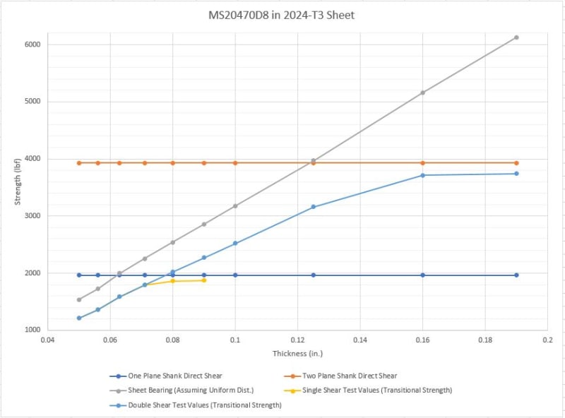
As I mentioned above, strength values given in the spec are not really to be relied on. For tension, that would simply be the Ftu of the shank material multiplied by the shank cross sectional area. Joint strength tables in an SRM or elsewhere are usually transitional shear strength data, so not what you want for tension either.

To calculate a tension allowable I would recommend using principles for threaded fasteners from a machine design textbook like Norton or Shigley. (Shigley sections 8-4 through 8-12, Norton, "Machine Design", sections 15-5 through 15-12).

Keep em' Flying
//Fight Corrosion!
 
why calculate a tension allowable, when MMPDS publishes values (table 8.1.5) ?

another day in paradise, or is paradise one day closer ?
 
MMPDS provides the most basic calculation... for example Table 8.1.5(b1)... the tensile strengths published are simply the minimum minor area of the fastener multiplied by the fastener material tensile strength.

IE for fastener diameter = 0.375, minimum minor area is 0.082397. Multiply by 55,000 psi = 4,531.8 lbf. The table reads 4,530 lbf.

This does not in any way account for other variables affecting tensile strength like sheet thickness (for pull-through), washer installation, preload, collar usage, or even head tpye etc.

Instead there is simply note h:
"nuts and fastener heads designed to develop the ultimate tensile strength of the fastener are required to develop the tabulated tension loads."

That is of course, not always the case - it is not uncommon for the collar to be the limiting factor.

I am encouraging people to understand the calculations which are not encompassed by reading off a table which can be misleading. As I mentioned above, the numbers listed on the spec (and in MMPDS) are simply based on Fsu or Ftu x Area. That is the upper limit of the strength envelope and not always accomplished in a real joint.

Keep em' Flying
//Fight Corrosion!
 
LD, Rb... Hmmm another perspective, this subject...

NAS1348 FASTENERS - RECOMMENDED TENSILE STRESS AREAS FOR EXTERNAL THREADED...
States that for .3750-24 nominal Tensile area for a 3A thread is = 0.0951-in^2 X 160000-PSI = 15,216# UTS

Per NAS4002 FASTENER, ALLOY STEEL,EXTERNALLY THREADED, 160 KSI Ftu, 95 KSI Fsu, 450 ºF...
TABLE III − TENSILE AND SHEAR STRENGTH VALUES, LBF MIN...
For 0.3750-24 ##Type I bolt style = 15200# UTS

##Type I -> typical => Tension head (hex, double hex, etc.) without a recess drive, long thread, (i.e. NAS6603-6620)

Based on this comparison, the MMPDS Table 8.1.5(b1) value for 0.3750-24 [UNF threads] bolt @ 160000-PSI = 13150#** UTS is conservative [relative to min breaking specification-strength for NAS4002]

MIL-S-7742 threads... or 13400# UTS for AS8879 [UNJF threads]

Regards, Wil Taylor
o Trust - But Verify!
o We believe to be true what we prefer to be true. [Unknown]
o For those who believe, no proof is required; for those who cannot believe, no proof is possible. [variation,Stuart Chase]
o Unfortunately, in science what You 'believe' is irrelevant. ["Orion", Homebuiltairplanes.com forum]
 
yes, I'm aware that MMPDS (and calcs based on Ftu) are for fully effective bolts, and you need to account for sheet thickness (and obviously CSK head).

another day in paradise, or is paradise one day closer ?
 
Status
Not open for further replies.
Back
Top