Continue to Site

Eng-Tips is the largest engineering community on the Internet

Intelligent Work Forums for Engineering Professionals

  • Congratulations KootK on being selected by the Eng-Tips community for having the most helpful posts in the forums last week. Way to Go!

Fastening design for bending moment of bolted profiles

Status
Not open for further replies.

GoncaloPT

Structural
Jun 9, 2020
24
Hi!
I'm in need of some assistance, and hopefully someone here can help me :)
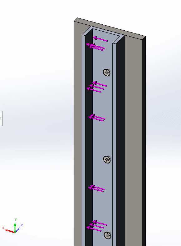
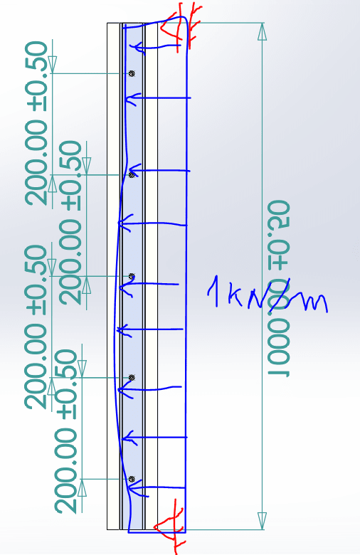
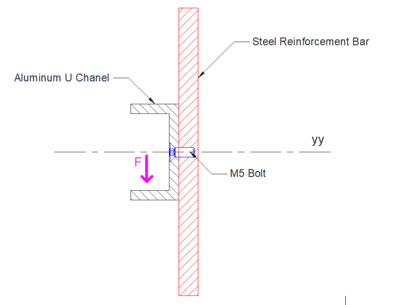
I have an aluminum U chanel that where a cladding will be fixed. This cladding will transmit forces according to the scheme below.
This forces will tranlate on a bending moment according to the yy axis on the aluminum chanel and steel bar.

Can someone help me on how to properly design the spacing and specifications of the bolt for a specific Bending moment on yy?
How can I calculate the shear forces?
image_fwuclz.png
 
Replies continue below

Recommended for you

Hi GoncaloPT

How long is the channel and what is the value of the F force, if your load is downward as shown I would put a row of bolt/screws nearer to the top side of the channel but we really need more info.

“Do not worry about your problems with mathematics, I assure you mine are far greater.” Albert Einstein
 
Shear force will be equal to F. There will also be shear as a function of bending moment. I would want there to be enough bolts to develop the clamp load to produce the friction to react F (keeping in mind the channel clamp load to the plate will vary due to bending). I would also want to relieve the area around the bolts (either on the channel or the plate) so the clamp load was taken at a larger radius.
 
Hi desertfox and BrianE22,
Thank you for your reply,

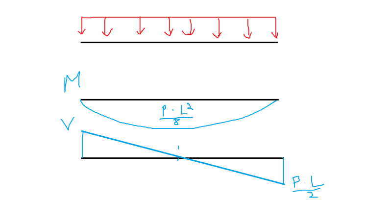
Perhaps I was not clear at first. Imagine this as a simply supported beam subject to loads on the yy axis. The maximum moment would be (P*L^2)/8.
This bending moment would develop some shear forces on the bolts. This is the force i'm interested in designing.

image_vzr6is.png
 
Hi again

What are the values of the forces, how many bolts and what are the dimensions of the channel?
Without some proper info we can only guess, what are you treating as a simply support beam? Is it the bottom flange of the channel?

“Do not worry about your problems with mathematics, I assure you mine are far greater.” Albert Einstein
 
GoncaloPT,

I recommend not using flat head screws into tapped holes for any sort of inaccurate assembly. Between the countersink and the tapped hole, you have no room for fabrication errors.

--
JHG
 
Hi Guys!

I was thinking on a hypotetichal case. But to have some values heres an example:
Imagine a 1 m simply supported beam, subjected to F=1kN/m. The spacing between the 5 bolts is 0.2m.
@drawoh , thank you for your suggestion. This is just an theoretical case, as i'm planing on doing a series of solutions like this.

image_s7hjhy.png
 
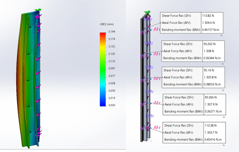
This is the expected forces I got from my FE model, but I would like to have this done trough hand formulae.

image_b8kuaj.png
 
Hi Again

Right well for starters it’s not a simply support beam because the bolts actually make it a statically indeterminate beam, I need sometime to sketch an example of how I would solve this assuming that the channel is rigid. I will post later.

“Do not worry about your problems with mathematics, I assure you mine are far greater.” Albert Einstein
 
GoncaloPT -

Are you looking at the scenario where the bolts come loose and have to react the shear force? Even then it can be tricky if some of the bolts stay kind of tight so the bar rotates and translates through the bolt clearance holes.
 
Hi again

Just looking again at your last post, Am I right saying the steel reinforcing is actually the simply supported beam but it’s loaded via the aluminium channel section through the bolts?

“Do not worry about your problems with mathematics, I assure you mine are far greater.” Albert Einstein
 
Hi @desertfox

Yes, you are right. Thank you again for your time and promptitude.
 
Does anyone know how to properly calculate the shear force across the lenght of the bar? This would help desiging the bolts.
Normally, I would assume that the diagram, but this would imply that the shear force on the middle bolt would be 0, that is not true according to my FE model.


Sem_T%C3%ADtulo_knqjzh.png
 
GoncaloPT,

You are doing the first stage of double integration method. Your shear forces go across the bar, not along it.

You could model your distributed load, and treat each screw as a solid reaction point. The bending of your bar might be interesting.

--
JHG
 
Status
Not open for further replies.

Part and Inventory Search

Sponsor