Continue to Site

Eng-Tips is the largest engineering community on the Internet

Intelligent Work Forums for Engineering Professionals

  • Congratulations KootK on being selected by the Eng-Tips community for having the most helpful posts in the forums last week. Way to Go!

fatigue of complex riveted joint - bypass load

Status
Not open for further replies.

ahkrit

Mechanical
Apr 18, 2021
30
Hello.

i would like to know how the bypass load in a complex riveted joint could be calculated? The fasteners are modelled with bush elements and the neighbouring shell elements show different von Mises stresses. The load propogation also not clear as the joint is complex and has 3D load case ( each end has different loads and moments). So the basic calculations like in Niu`s book do not really help in that case.
How could a fatigue calculation work in that case?

Thanks in advance!
 
Replies continue below

Recommended for you

I would try and fit your model results to the typical loading at a hole problem ... fatigue or DTA.

You have the load transferred at each fastener, and many solutions use a bearing stress.

But you may want the upstream stress and the downstresm stress and pinload stress is upstream-downstream.

Without knowing the detail of your model (it sounds very detailed) it's hard to know how difficult it is to estimate these stresses from the results.
And do you use von Mises or max principal ?

It may be worth investigating a dedicated fatigue analysis FEA post-processor like "ncode".

another day in paradise, or is paradise one day closer ?
 
I suggest that you create a simple 2 fastener axially loaded joint model, using the same modelling approach as the large model. The bypass loads can be calculated by hand. Then run the simple model and work out how to post process the results to get the correct bypass loads. Then generalize the approach to the large model.
 
@SWComposites

i understand you point "start with simple modells and look how it works there" but that is my problem that i can find simple lap joints everywhere, which is far away from my model.
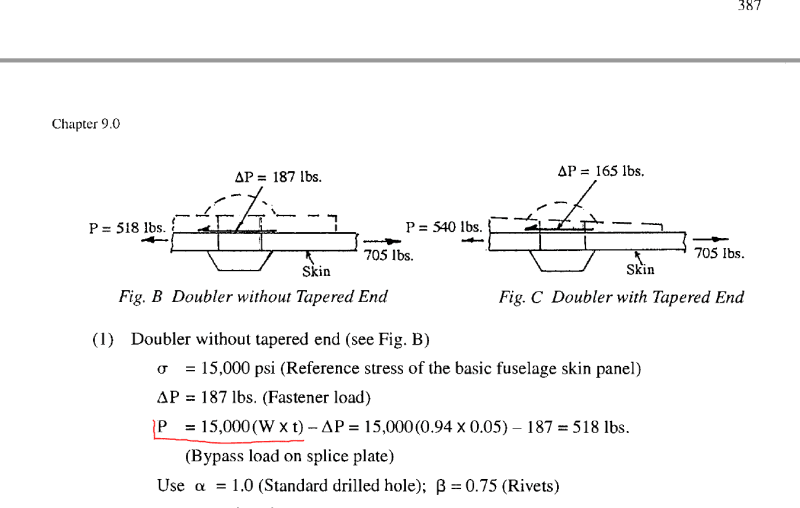
As in Niu`s book here
Niu_book_bypassload_kablnu.png

for a simple one-dimensional, tensile stress the bypass load = total load - fastener load, what i cannot really do in a joint what i am calculating. So how could it be done as soon as the geometry is complex and the loads are not only one dimensional?

@rb1957

I can evaluate max principal as well i just do not know how, as it is not an easy load case.
What do you mean by upstream-downstream?

@rb1957 @SWComposites

If you look at this joint i am trying to calculate similar ones with Abaqus. Different profiles riveted together through sheet metal parts. The discretisation is similar as on the webpage, but i am trying to solve it now as suggested in other threads( bigger shell elements app. 10mm side length and fastener elements defined on the nodes at the connection points. BC: all the profiles have 3D loads (forces and moments in all directions).

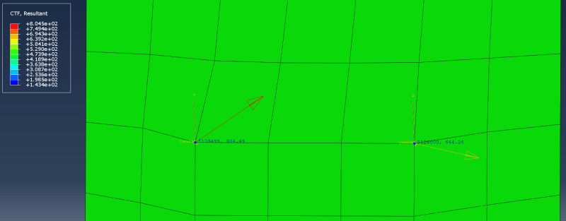
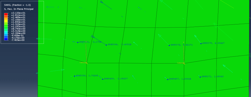
On these two pictures below you can se a part of the joint where the connection has 2 rivets next to each other. So how could one get the bypass values in such a case to be able to perform a fatigue calculation according to Niu`s Book?

2_fastener_fastenerloads_advgmw.png
2_fastener_maxprincipal_ruobjq.png


Thanks in advance!
 
"upsteam" and "downstresm" refers to locations before and after the load transfer so the Pdownstram + Pinload = Pupstream, Pdownstream is Pby-pass.

I doubt you'll find more than you already have, by way of analysis models. Niu has a simple procedure based on the load transfer and the by-pass stress and fastener geometry.
At each fastener you know the load transfer, right? So how to approximate the by-pass stress ? from your mesh you can average the stress from a couple on either side of the fastener.

another day in paradise, or is paradise one day closer ?
 
It looks like a compact bolt group, with loads predominantly in plane, is that right?
Can you conservatively assume the worst case fbr/ft for a particular fastener, and that way boil it down to a 1d problem? I recall doing something like that in the past, otherwise the analysis becomes very complex very quickly.
 
Ahkrit - you didn’t pay attention to my hint. Build a FEM of the simple 2 faster model. Figure out how to process the results to match the hand calc. This will give a procedure that can be generalized.
 
OK. First. Von-Mises stress is not a stress, it is a scalar value of a failure theory. Second, with metals you do not address bypass stresses. Third, If you are doing an ultimate analysis you cannot use the model fastener loads, if you hare doing a linear distribution, unless you are correctly modeling your fasteners (and you are not if you are using cbush elements) you will get the wrong load distribution.

Your entire problem is constructed improperly and it would take too long to explain how to perform this very simple and basic calculation here. I'd suggest you get a stress analyst who has some experience (this is the sort of problem someone with 6 years of experience should be able to handle easily) and ask them how to set it up. I've been seeing way, way too much of this sort of incorrect stress analysis the past ten years or so. Please stop. It's completely wrong.
 
Joe Moore: Bypass stress is a major consideration in fatigue analysis.
Don't shut down a valid question if you don't have an answer.
 
@Ng2020

yes, the loads are mainly in plane( meaning mostly shear loads are on the rivets) but i still would like to (probably have to) take axail loads into account as it can change the results at few joints.
What does fbr/ft mean exactly? Boiling it down to 1d problem is also not clear.


@Joe Moore

Thanks for your comment. It is clear that Von-Mises is scalar value, it was not the main point of my question.
"With Metals you do not adress bypass stresses"? Is it really so because what i found so far in forum threads and including Niu`s book says so.. Could you maybe give some reference where it is cleared, if it is really wrong?
Actually i do not use CBUSH elements but in the model posted above are the fastener elments form Abaqus are used. (as far as i know distribution is also included which should help against mesh-size-dependency stiffness problem.

@ Everyone

But anyway regarding stiffness modeling approaches there are several documents, papers which can help a lot. But what about the rest of the approach for a fatigue or ultimate calculation? Regarding that i am looking for some answers.

The structure`s geometry is "kind of complex" (and i am sure i am not the first one with such problems especially if we think about aircraft structures) still i could not find any 100% clear exaplanation of calculation procedures for a bit more complex joint calculation for ultimate and/or fatigue load cases.

Regarding stiffness and model build up approach there i found some useful informations (from ESPcomposites mainly).
espcomposites_comment_forum_gqdb7f.png


So lets say there is a joint with complex loads and properly built-up modell with correct stiffnesses:
1. How could one predict/evaluate from a FEM calculation a Net section stress for ultimate loadcase?(especially if the holes are not included in the model as on the other comments suggested.) Correct me if i am wrong but that would be the only neccessary failure mthod to check as the bearing and shear of the rivets could be checked simply by calculating Connector shear force/given shear or bearing area.

2. How could one predict/evaluate from a FEM calculation bypass stresses for fatigue calculation? or should i take a step back and ask "a whole fatigue calculation" if bypass loads are really unneccessary? What are the loads/stress values/whatever, which are evaluated..?

I would really appriciate some useful answers. Thanks in advance!
 
Thanks Bragi. These are master's thesis summaries, parroting back the method as the student was taught and followed. Not bad if you want to refer to a sequential approach without the analytical details, or you just want to see "what the result looks like".

If you want the real details and the full understanding, go no further than Jaap Schijve's book, Fatigue of Structures and Materials. If I'm not mistaken, this book is the first time all of the diverse test data and analytical methods of fatigue and fracture mechanics were brought together in a form that can guide a practical structural analysis. You can certainly find older works, such as Swift's papers and tons of S-N charts from aircraft OEM's but they aren't the whole picture. FAR 25 requires Fatigue AND Damage Tolerance. Emphasis on the "AND".
 
Thanks Bragi for the links.
Not bad documents indeed.

However i would like to see the fatigue calculation process. As asked above for Niu`s method about the bypass load especially.
Regarding rivets stiffness calculation there are many documents available. Unfortunately the rest of the calculation process is not really mentioned anywhere ( or the best what ones can find is simple tensile test case like in Niu`s book)
This is my problem i am trying to overcome. What would be a reasonable approach for fatigue calculation of many rivets in structure without very detailed modelling?
Like in Niu`s approach, but if this would be the way then how could one find the bypass load for complex load case as posted above?

or would be in complex loadcase scenarios neccessary to model all the holes and have the local 1st principal stress evaluated for fatigue?

Cheers!
 
have you considered using a packaged code, like ncode, to do you fatigue analysis ?

you don't need to analyze every fastener. I'd look at the group ...
1) which fastener has the highest load transfer ? You should be able to get this from your FEA, depending on how you modelled the fasteners.
2) which fastener has the highest by-pass stress ? This'll probably be one of the outer fasteners.

If fastener diameter and plate thickness varies then you may want to look at mode fasteners, but I'd've thought one conservative analysis should cover all. Of course if too conservative, then a couple of analysis sites, but every fastener seems extreme.

But then in the age of spreadsheets ...
1) list the fastener load
2) list the plate thickness, the fastener diameter
3) you can then calculate the bearing stress, which is important to fatigue
4) you can list the principal stresses around the hole. You'll probably need the maximum principal stress (as representing the remote tension) and the lower (representing the by-pass stress). You have 4 elements around the hole ... two should have a higher principal than the other two ... it should be quite obvious.
5) from this you can calculate the Kt.

another day in paradise, or is paradise one day closer ?
 
There are many theoretical/test reports regarding these type joints... published by DoD/NACA/NASA/Universities.

Extreme caution is required. These reports are only valid with industry standard materials, finishes, parts and good/consistent riveting quality, IE: hole size/quality, alignment/spacing, bucking/squeezing consistency, etc.

Regards, Wil Taylor
o Trust - But Verify!
o We believe to be true what we prefer to be true. [Unknown]
o For those who believe, no proof is required; for those who cannot believe, no proof is possible. [variation,Stuart Chase]
o Unfortunately, in science what You 'believe' is irrelevant. ["Orion", Homebuiltairplanes.com forum]
 
What i would be really interested in is still how to calculate a bypass load in different structures, where the members cannot be modelled as simple beam elements as Niu does in his book.
For example on the shell model posted above, there is a bending load, which is transfered through the fastener elments, meaning all shows in different direction and thus the force flow is not as one directional as at a simple tensile load case.
What could be done in that case for calculating bypass loads?

@rb1957

would you be so kind and explain a bit more about the steps you wrote please? The first 3 points are clear.
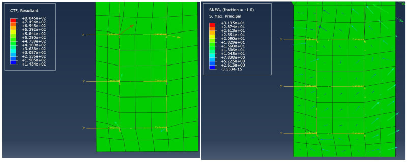
You can see a part of the steel plate from a complex joint below, fastener forces and the max principal stresses. The fastener forces tend to give back a reaction to bending.
How could i deal with point 4. and 5. in that case for example? Thanks!

fastener_force_and_principal_stress_ejfo1x.jpg


cheers!
 
Status
Not open for further replies.

Part and Inventory Search

Sponsor