Continue to Site

Eng-Tips is the largest engineering community on the Internet

Intelligent Work Forums for Engineering Professionals

  • Congratulations waross on being selected by the Eng-Tips community for having the most helpful posts in the forums last week. Way to Go!

Fault Current Analysis

est19

Electrical
Jan 21, 2025
1
Hello everyone, my first post here.

I was modelling a power system that has the following fault utility source contribution values:

3LG fault: 7050A at X/R = 5.25
1LG fault: 5700A at X/R = 4.73

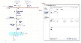
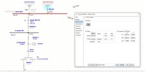
When trying to fault the main bus connected directly to the utility, I get a Line-to-Ground fault current value above 7kA which is higher than the utility’s contribution. There is a 3-winding stepdown transformer (Yn-D-Yn) downstream, and I've disconnected everything else downstream beyond that transformer.

Can anyone please help me get clarity on and understand why the L-G values are appearing higher than the utility contribution values on that main bus? Is the transformer playing a role in this? Not sure what I'm missing here and seeking some help to better understand this.

Attaching some model screenshots for a visual reference.

Thank you.
 

Attachments

  • 22.JPG
    22.JPG
    125.1 KB · Views: 15
  • 33.JPG
    33.JPG
    127.9 KB · Views: 13
Replies continue below

Recommended for you

Yeah, you've got a bunch of fault current coming back from the transformer.
 
The delta winding will backfeed into a single phase fault.
 
Does your power system model allow you to see branch fault currents? If it did you’d see 1500 A or so of current from that YDY transformer - it’s functioning as a grounding bank to provide ground fault currents.
 
Electrical Engineering General Discussion:
I have seen this effect upstream of connected-neutral wye:delta banks.
Under non fault conditions, a wye:delta bank will backfeed an un-energized phase with full voltage.
The voltage drop under load will be increased above normal due to the added impedance of the wye:delta transformer.

To model the condition, think of three independant transformers in a bank and consider the unfaulted phases to act as an open delta.
Now consider the faulted phase transformer as a short circuited load across the third transformer.
The available fault current will be limited by the combined impedances of all three transformers.
The calculation of the peak offset current may be complicated as the point on wave will be different for each transformer and the currents in the unfaulted phases will be at 50% PF, one phase lagging and one phase lagging.

Many times I have sat in my room on the island while the small utility recovered fro an outage by switching in one phase at a time, manually.
WE had a couple of wye"delta banks on the system.
First phase goes in: Lights come on dim, about 50% voltage on each unpowered phase.
Second phase goes in: Brightness of lights increases. Not quite full brilliance due to the regulation of the wye:delta banks back-feeding the open phase.
Third phase goes in: The third phase is now fed directly and the lights go to full brightness.

Yes the wye:delta bank will back-feed upstream.
Back in the day of conversion from delta systems to wye:delta systems (40s to late 60s) it was a known effect that a shorted phase would result in fuses blowing through-out the distribution circuit.
Browse some old text books and you will find this mentioned.
The cause?
Overloaded wye:delta transformer banks through-out the circuit back feeding into a shorted phase.

Personally I would calculate the contribution to a single phase fault based on three individual transformers in a bank.
I would use three times the %imp of one transformer to calculate the ASCC for a back feed.
Or 1/3 of the ASCC of the three phase bank.
That should be safe for sizing protection devices as they are rated in ASCC Amps.
(More anecdotes on request. This effect will often cause customer damage. I have many times worked with customers to avoid this damage on systems that included wye;delta transformer banks.)


--------------------
Ohm's law
Not just a good idea;
It's the LAW!
 
What is the MVA rating of the Yndyn transformer directly connected to the Utility bus?
 
If the tertiary winding is grounded,Short circuit at secondary three winding transformer  when the teriary is grounded.jpg then the total impedance of the system decreases.
 
Grounding the delta has no effect on system impedance.
The grounded wye:delta connection has the ability to transfer power from one phase to another.
The impedance seen by line to line unbalances or faults or line to neutral unbalances or faults is less. (whether the neutral is grounded or not)
Grounding the supply side neutral is important because then line to ground faults are also line to neutral faults.
The effect is caused by line to neutral unbalances, whether grounded or not.
I spent years in an area where wye:delta connections were common and inherited some wye:delta banks when I became system engineer for a micro-utility.
I once had a customer's wye:delta bank go up in smoke due to circulating current in the delta caused by badly unbalanced primary voltages. (This was not on my system. This was a customer on the National Grid.)
 
Last edited:

Part and Inventory Search

Sponsor