Hello.
I have a case, that probably is easy to explain, but that I'm stuck on for the moment.
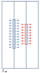
In picture below there are 3 plates connected to each other by guide pins.
The left and right side of the 2 outer plates are fixed.
Blue and red areas are cavities where a pressure is applied.
In this example the forces on the blue cavities are F=10000N and on the red cavities F=4000N
As I see it the result forces acting on the left plate fixture should be Z= +10000N.
The forces acting on the right plate fixture should be Z=-10000+4000-4000 = -10000N.

Trying to verify this with FEA gives result force 10000N. All good so far.
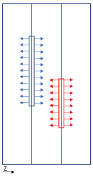
But what happens if the cavities are off centre?

With my simplified FBD, the resulting forces should be the same.
Even if the red area would be increased, as long as its force is below 10000, it shouldn't add to the result force.
Doing a FEA on this example gives a result force of 10500N (25% addition from the 4000N force)
Moving the red cavity down even further, completely off centre (edge to edge) gave a result force of 12000N (50% addition from the 4000N force)
What am I missing?
Thank you in advance for your time.
I have a case, that probably is easy to explain, but that I'm stuck on for the moment.
In picture below there are 3 plates connected to each other by guide pins.
The left and right side of the 2 outer plates are fixed.
Blue and red areas are cavities where a pressure is applied.
In this example the forces on the blue cavities are F=10000N and on the red cavities F=4000N
As I see it the result forces acting on the left plate fixture should be Z= +10000N.
The forces acting on the right plate fixture should be Z=-10000+4000-4000 = -10000N.

Trying to verify this with FEA gives result force 10000N. All good so far.
But what happens if the cavities are off centre?

With my simplified FBD, the resulting forces should be the same.
Even if the red area would be increased, as long as its force is below 10000, it shouldn't add to the result force.
Doing a FEA on this example gives a result force of 10500N (25% addition from the 4000N force)
Moving the red cavity down even further, completely off centre (edge to edge) gave a result force of 12000N (50% addition from the 4000N force)
What am I missing?
Thank you in advance for your time.
