Eng-Tips is the largest engineering community on the Internet

Intelligent Work Forums for Engineering Professionals

FE modelling of three-edge supported plate under simply-support 1

Status
Not open for further replies.

Jb2024

Structural
Jun 16, 2024
1
0
0
AU
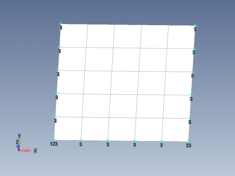
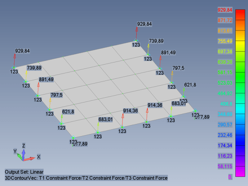
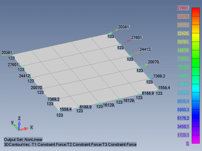
I am carrying out some FE modelling o plate using simply-supported along three edges. I am wondering how I could go about applying boundary conditions on the FE software, preferably Strand7. The scenario is that the plate is subjected to uniformly distributed load on its face and I need to investigate the maximum tension and deflection for varying loads. all replies are welcome. appreciate it
 
Replies continue below

Recommended for you

I’m interested in your post and will be keen to see what recommendations you receive. The reason being is that I’ve written a template (personal interest only and not checked) using rectangular plate theory for the same case you describe, and I’m looking for an FEA approach for comparison. It does correlate well with Roark, but I’m looking for higher precision in the decimal constants for stresses, BM, etc.
 
I am not a Strand7 but I assume that you can and know how to fix any of 6 DOFs in any particular node in your mesh. Than you should use 3-2-1 method to apply additional support to model.
Here is an example, plate located in XY plane and pressure is applied normal to plane. Numbers near nodes are fixed DOFs 1/2/3/4/5/6 -> TX/TY/TZ/RX/RY/RZ.
1_elxel9.png

As you can see plate edges can move free in XY plane.
1_fg43rf.gif
 
1-Constrain edge translation in vertical axis only. (If required)With additional constraint of one of the corner in both lateral direction to avoid rigid body motion. All rotations free.

2-Another "complex" but more accurate approach would be to define support surface below plate edges and define contact between support surface and plate with frictional/frictionless contact just like it will be actually supported. Note that support surface needs to be optimum width to avoid slipping of edges from contact due to low width or large part of plate surface getting supported.

Considering contact convergence hassle and other time consuming activities, option 1 looks easy and quick fix.[bigsmile]
 
could you mirror the plate across the unsupported side, and then consider a 4 side simple support ?

Zero stiffness in-plane (as 1 and 1st reply) is clearly one end of the solution ... and we don't know the loading so we don't know how significant are the in-plane loads. Any in-plane loads would invalidate this approach. Response to pressure loads is questionable.

"Hoffen wir mal, dass alles gut geht !"
General Paulus, Nov 1942, outside Stalingrad after the launch of Operation Uranus.
 
I think karachun's reply answers your question, but for more background information, if you have access to the Strand7 Web-notes you will find many examples there of plate analysis, and you can also now download the full Verification Manual, which includes data files for all the verification models.


Doug Jenkins
Interactive Design Services
 
I'm a little bit surprised that the lower right node is not moving in x, but I suppose that is because it is a linear analysis. I am very surprised that the upper corners move apart.


That is, take a matchbox tray, rip one end off. Put your finger in the middle of the free edge, The sides will move inwards, never outwards, doesn't matter which way vertically you push. Perhaps we are looking at an animator artefact.

Cheers

Greg Locock


New here? Try reading these, they might help FAQ731-376
 
GregLocock

It moves, here is zoomed view.
2_s3ahx0.gif

I made nonlinear analysis (SOL106, Nastran) with geometric nonlinearity.

GregLocock said:
Perhaps we are looking at an animator artefact.
Yep, that`s what I get when use animated view with setting Linear-Full in Femap. Here is better animation with intermediate nonlinear results.
3_nli1bn.gif
 
With respect to the upper corners moving apart: yes, that is indeed a common animation artefact that you'll often see when linear solutions are animated from -1 to +1 times the applied load.

The animation routine has only two sets of actual displacements to work with: zero load / zero deflection; and applied load case / resulting deformations. The deflections are generally amplified (by a factor of 100 or so) to aid visualisation. The animation routine may then generate another "negative" displaced shape using -1 times the calculated deformations, to approximately simulate a negative load application, as well as a number of intermediate steps to cycle through.

In a case like this, if you actually analysed a negative load case, you would find the upper corners both move inwards, just like the load case which has been analysed. However, the animation routine shows the upper nodes moving outwards by an equal and opposite amount to how much they were calculated to move for the positive load case.

If you only animate from zero load to applied load, you won't see this spurious behaviour - it is only apparent when animating from -1 to +1 times the applied loads.

 
Status
Not open for further replies.
Back
Top