Eng-Tips is the largest engineering community on the Internet

Intelligent Work Forums for Engineering Professionals

FEA: Boundary conditions when modeling nozzle connections in pressure vessels

Status
Not open for further replies.

fem.fan

Mechanical
Jun 7, 2021
33
0
0
AR
hi, every time i model a nozzle connection i come across the same problem: " how much shell to model". i have tried many options but none of them quite satisfies me.

if i model the whole circumference of the sheell with solid elements, it takes a lot of elements and thus, a great computational cost.

i tried modeling just a part of the circumference applying symmetry conditions, say 1/4 or 1/2 of shell, but it doesn´t seem right since the symmetry is not real.

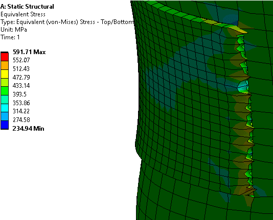
my last and final approach was to model a great part of the shell with shell elements, the nozzle and its surroundings with solid elements and then coupling them with multipoint constraints. this was a great solution for elastic material problems, but when using elastoplastic materials as per ASME - VIII div. 2 part 5 the rigid connectiones provoked a convergence issue due to highly concentrated unrealistic plastic srtains.

these images illustrate each option.

full circumference with solids
Captura_cmt2li.png


1/4 of circumference with solids
Captura_tmwlxo.png


shell to solid coupling
Captura_yvhigd.png


highly concentrated plastic strains
Captura_lsh1cj.png


can anyone give some insight on the matter?

thanks in advance.
 
Replies continue below

Recommended for you

This model is partially symmetric (unless it’s loaded asymmetrically for some reason). You can apply symmetry in Z and Y direction but the cut must go through the nozzle itself as well.

Apart from that, I would use submodeling.
 
thanks for your reponse, but the model is not symmetric for two reasons, 1- the loads applied on the nozzles are not symmetryc 2- this is a simple model i draw to illustrate my point, but the real geometry is much more complex...

regarding submodeling, it has two problems, 1- as i said before, this is not the true geometry, and the real one cannot be modeled with sell elements due to its complexity. making a global model with a coarse solid mesh would be wrong since shell structures are not well represented by large solid elements (shear locking and bad shape of the element) 2 - it generates the same concentrated loads as in MPC.

this is the real geometry...
Captura_ogzsox.png
 
solid meshing the entire tank is (forgive me) "lazy". I think you need to model the entire tank. I would mesh the major portion with 2D shells (I'd probably start by modelling the entire tank this way, without your pipe fttg, to ensure a clean starting point. Then maybe add the pipe fttg as an RBE to see the effect of the pipe loads on the tank. Then a local 3D mesh to study the interface between the tank and your fttg in detail.

Don't know the relative magnitude of the loads ... are teh pipe loads significant compared to the tank loads (pressures) ?

another day in paradise, or is paradise one day closer ?
 
I've been guilty myself of being "lazy" ... just modelled a frame with 1000000 3D TET10s ! ok, so it took 45 minutes to solve ... not a big deal. ok, so I had to use an external 2TB drive for scratch space ... no biggie.

another day in paradise, or is paradise one day closer ?
 
I don’t know how it works in Ansys but Abaqus allows for so-called shell-to-solid submodeling where the global model has shell elements and the submodel has solid elements. It’s a nice technique to be used in cases like this one.

Also, there are two types of submodeling depending on the driven variable - the most node-based (displacements from the global model are applied to submodel) and surface-based (stresses from the global model are applied to the submodel). Node-based submodeling is the more versatile and common approach, allowing also for the aforementioned shell-to-solid submodeling. Maybe that’s the way to go in this case. Other FEA programs may offer similar types of submodeling technique.
 
I'd model the shells at mid-thickness (where else ?) and along the perimeter of the 3D model just "RBE" the solid nodes to the shell nodes (which is "all" the programmed tool is doing).

another day in paradise, or is paradise one day closer ?
 
rb1957 - that´s exactly what i did and said before that with elastoplastic material the RBE elements generate unreal plastic strains tha make the simulation fail to coverge... please see the image in my first post
 
ok, mea culpa. the displacements along the edge look "funny", too jagged. the 3D nodes that don't align with the 2D mesh look "inactive" ? mesh refine the 2D elements along the edge ? make sure that you're transferring moment across the boundary, solids only have 3 dof and moment is the difference between the inner and outer faces.

have a look at the displaced shape.

another day in paradise, or is paradise one day closer ?
 
or maybe this is "just" a modelling "artifice" if the high stresses are local to the boundary and not closer to your fitting ?

another day in paradise, or is paradise one day closer ?
 
that´s correct, they are local, however the problem is that the simulation diesn´t converge due to plastic instability... with elastic material works fine and the reuslts are correct. the problem is with the plastic material
 
I would test your NL material on a test piece ... simple tension specimen.

another day in paradise, or is paradise one day closer ?
 
FEA_way said:
I don’t know how it works in Ansys but Abaqus allows for so-called shell-to-solid submodeling where the global model has shell elements and the submodel has solid elements. It’s a nice technique to be used in cases like this one.

ANSYS can do the same, here's a tutorial on a structural problem.
 
You can use two materials to eliminate convergence problems/ I assume that problems caused by large element distortion at solid-shell interface.
1) elastic material in region close to solid-shell interface, we assume that plasticity occurs only at conjunction of pipe and nozzle, if hoop stress is greater than sigma_y then we have nothing to calculate, whole structure is too weak;
2) plastic material near nozzle to capture real plasticity.
 
karachun - the whole vessel undergoes plastic strains, since ASME VIII div. 2 part 5 requires to evaluate the structure for 3.5 times the design loads...

i´ve tried your approach and it works, but naturally, the structure is virtually stiffer in that area giving erroneus results within the near-to-nozzle zone.
 
how many pressure cycles in a lifetime ? Can't be that many (by my estimate, if 3.5*hoop > fty).

another day in paradise, or is paradise one day closer ?
 
80, give or take, why? the problem is not in cyclic loading but in plastic collapse evaluation. it´s only a numerical problem.
 
I was thinking that your working stress was high, and so a short fatigue life.

but it sounds like you're doing a "worst case" scenario, forcing the tank to be plastic ?

Have you tried running your NL material in a small test case ? Your modelling approach seems valid, but I'm surprised by the stress spikes at teh 3D nodes which are not connected to 2D nodes (as it looks in your pic). maybe mesh refine the shells so there is a one-to-one node alignment with the 3D mesh ?

another day in paradise, or is paradise one day closer ?
 
yes, i´ve tried with different mesh sizes relative to each other in sample problems and it keeps happening...

all nodes on the 3D face are connected to some of the nodes on the 2D edge, that is what the program does.
 
"all nodes on the 3D face are connected to some of the nodes on the 2D edge, that is what the program does." that's not what the pic shows, if the black lines show element edges.


another day in paradise, or is paradise one day closer ?
 
Status
Not open for further replies.
Back
Top