Continue to Site

Eng-Tips is the largest engineering community on the Internet

Intelligent Work Forums for Engineering Professionals

  • Congratulations KootK on being selected by the Eng-Tips community for having the most helpful posts in the forums last week. Way to Go!

FEA: Boundary conditions when modeling nozzle connections in pressure vessels

Status
Not open for further replies.

fem.fan

Mechanical
Jun 7, 2021
33
hi, every time i model a nozzle connection i come across the same problem: " how much shell to model". i have tried many options but none of them quite satisfies me.

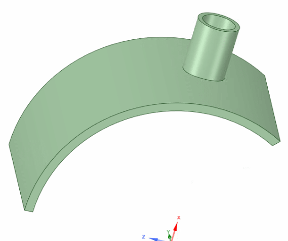
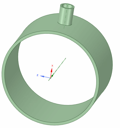
if i model the whole circumference of the sheell with solid elements, it takes a lot of elements and thus, a great computational cost.

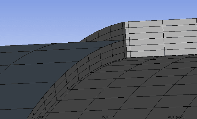
i tried modeling just a part of the circumference applying symmetry conditions, say 1/4 or 1/2 of shell, but it doesn´t seem right since the symmetry is not real.

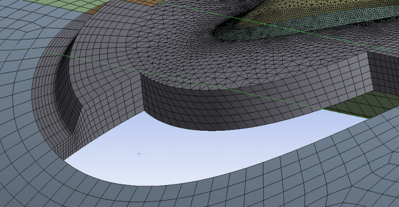
my last and final approach was to model a great part of the shell with shell elements, the nozzle and its surroundings with solid elements and then coupling them with multipoint constraints. this was a great solution for elastic material problems, but when using elastoplastic materials as per ASME - VIII div. 2 part 5 the rigid connectiones provoked a convergence issue due to highly concentrated unrealistic plastic srtains.

these images illustrate each option.

full circumference with solids
Captura_cmt2li.png


1/4 of circumference with solids
Captura_tmwlxo.png


shell to solid coupling
Captura_yvhigd.png


highly concentrated plastic strains
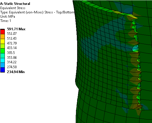
Captura_lsh1cj.png


can anyone give some insight on the matter?

thanks in advance.
 
Replies continue below

Recommended for you

rb1957 - the approach that fem.fan is taking is using an LRFD approach as permitted/required in ASME Section VIII, Division 2, Part 5, 5.2.4: Elastic-Plastic Analysis Method for demonstrating Protection Against Plastic Collapse.

I would put any element-type transition 2.5*sqrt(R*t) away from the edge of any discontinuity, such as your repad/insert plate.

I also don't have a problem with biasing the mesh towards having warning-level aspect ratios away from the area of interest, keeping the 3D-solid element approach. There's nothing going on out "in the back" anyways. And you'll still adequately capture the through-thickness plasticity.
 
TGS4 - let´s use another approach. how would you model the structure if you had to do it from scratch?
 
Solid elements (hexahedrals only) throughout. High aspect ratio elements in the back. Minimum of three quadratic elements in the through thickness direction. Mesh refinement study comparing averaged and non-averaged results - especially for Strain Limit Damage Ratio for satisfying Protection Against Local Failure (hopefully you're using asbestos and you can use the Ductile Damage Material Property).

You'd need the full model to demonstrate Protection Against Collapse From Buckling (so as to not exclude a non-symmetric buckling mode).
 
that would be ideal, problem is, it´s impossible to use only hexahedrals because of geometry coplexity. and modeling everithing with solids requires a ridiculous amount of RAM (i have 128 GB and i couldn´t do it), hence my mixed shell/solid approach...
 
That seems excessive. How many elements through-thickness are you using? Quadratic or linear elements?
 
six quadratic elements through thickness. but i also have tetrahedral elements where hexaedrals where impossible...
Captura_im7q20.png
 
ay caramba ! 13 nodes through the thickness ... how thick ? 1" ??

one thing that may (or may not) be relevant ... I see the 2D shell elements are on the OML (and not the mid-thickness plane) ? trivial for the pressure vessel I understand, but maybe important to this detail ?

so you RBE all 13 nodes and the 7 mid-side nodes to the 2D node ??

have you run the tank as a 2D mesh, without this detail ? I've modelled pressure vessels and found different results from different model constructions.

if you did that you could either ...
1) apply the boundary displacements to the detail model, or
2) reduce the farfield model to a stiffness element (or have you discounted the "super-element" approach ?)

another day in paradise, or is paradise one day closer ?
 
Three. Three quadratic elements through-thickness is sufficient. You've gone way overboard here. No wonder you are running out of memory...
 
i don´t understand, shouldn´t every case be evaluated independently by a mesh convergence study? i did that and this maesh was the result. how can there be a "general rule" for all the cases that three quadratic elements are sufficient? it depends on the stress and strains gradients
 
thx for skipping my post.

How linear are your 13 points ?

But 3 or 6 elements through the thickness is only a minor change (compared to the mesh density.

Why does this last pic (with the shell elements on the outer sure differ from the earlier pic (showing the shell elements at mid-thickness) ?

another day in paradise, or is paradise one day closer ?
 
rb1957 - the last pic shows only the solid part. what you are seeing are solid elements, the shells are out of the pic
 
Status
Not open for further replies.

Part and Inventory Search

Sponsor