Continue to Site

Eng-Tips is the largest engineering community on the Internet

Intelligent Work Forums for Engineering Professionals

  • Congratulations pierreick on being selected by the Eng-Tips community for having the most helpful posts in the forums last week. Way to Go!

FEA Boundary Conditions

Status
Not open for further replies.

AYou50

Mechanical
May 9, 2023
1
Hello everyone,

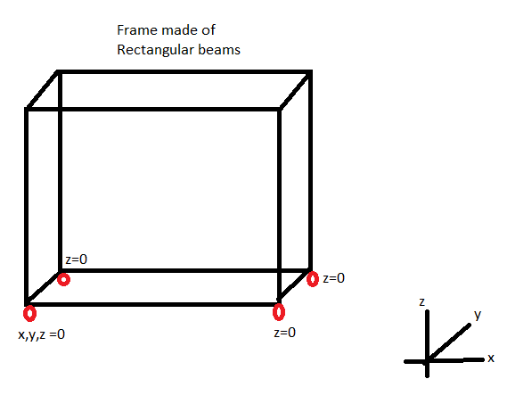
I have got a basic question with regards to the boundary conditions of a FEA model. It's a simple made of rectangular beams frame, supported with wheels bolted on to each of the four corners. I am looking at stresses and displacements in the frame.

I would like to get your opinion on the boundary conditions one would use in such set-up. I have blocked all displacements (x,y & z) on one of the supporting corners and blocked only the vertical displacements (z)on the other three corners. With regards to rotations, I have kept the model unconstrained for rotations around all three axes. A crude sketch of the frame is attached

Any ideas/suggestions are welcome

frame_om1jxg.png


Best Regards
 
Replies continue below

Recommended for you

I think that satisfies rigid body motion, but if I had my "druthers" I'd support each corner with three rods (in X, Y and Z) and constrain the ends of the rods. This gives the model the ability to have small deflections between the supports (deflections which rigid constraints prohibit.

"Hoffen wir mal, dass alles gut geht !"
General Paulus, Nov 1942, outside Stalingrad after the launch of Operation Uranus.
 
AYou50,

If your frame is unconstrained in X and Y in the real world, there is no way to impose side loads on it. Don't analyze for them.

Is your frame symmetric about X and Y. Analyze one quarter of it. I think this will let you constrain everything for vertical loads[ ](only).


--
JHG
 
"If your frame is unconstrained in X and Y in the real world, there is no way to impose side loads on it. Don't analyze for them." he needs X and Y constraint for rigid body motions, so I'll interpret this advise as constrain X and Y as shown, but you don't need to analyze these reactions (which should be zero in any case).

personally not a fan of symmetric models ... which also requires symmetric loads.

"Hoffen wir mal, dass alles gut geht !"
General Paulus, Nov 1942, outside Stalingrad after the launch of Operation Uranus.
 
Your model as shown in your diagram is unconstrained against ZZ rotation.[ ] (The XX and YY rotations are indirectly constrained by virtue, respectively, of the Y and the X distances between some of your Z constraints.)

If your unspecified FEA software can handle this, fine (but theoretically incorrect).[ ] If it cannot, then you need either to apply a ZZ constraint to a node or to apply an appropriately located X or Y constraint to one of your three Z=0 nodes.


[ ]—————————————————————————————————
Engineering mathematician/analyst.[ ] See my profile for more details.

 
If you have pneumatic tires or rubber casters, consider putting springs at the corner to account for deflections in the wheels/tires.
 
@denial ... damnit ! I had that written up then talked myself out of it (forgot to look at the Z rotation ... sigh). I was beguiled by the 6 constraints !

yes, you need another X or Y to create a couple about Z. Check that the X and Y constraint forces are zero and the Z constraints add to your applied load.

"Hoffen wir mal, dass alles gut geht !"
General Paulus, Nov 1942, outside Stalingrad after the launch of Operation Uranus.
 
You haven't stated what loading scenarios you're trying to analyze, which will affect how you constrain the model. You may need one or multiple sets of constraints if you're analyzing multiple scenarios.
 
JStephen brings up a very good point.[ ] Since the Z displacement is constrained at 4[ ]nodes it is over-constrained (by one).[ ] You need to put realistic Z-springs at each of those four points in order to get a realistic force distribution.

This overconstraining is probably why rb1957 was initially "beguiled by the 6[ ]constraints".[ ] I was briefly similarly beguiled.

[ ]—————————————————————————————————
Engineering mathematician/analyst.[ ] See my profile for more details.

 
I think we're over thinking this. Put the same stiffness on the four corners and I don't think it'll change the solution much ... not until the stiffness is as low as a member stiffness.

But still, remembering this is the student forum, it is a good exercise to run with a variety of Z stiffness (from infinite (hard constraint) to 1E4 or less) to see the difference.
I don't think it matters much on this simple frame, but it is an opportunity to learn and to stick something in the ol' toolbox.

"Hoffen wir mal, dass alles gut geht !"
General Paulus, Nov 1942, outside Stalingrad after the launch of Operation Uranus.
 
next we'll talk about the floor not being perfectly flat ...

"Hoffen wir mal, dass alles gut geht !"
General Paulus, Nov 1942, outside Stalingrad after the launch of Operation Uranus.
 
Status
Not open for further replies.

Part and Inventory Search

Sponsor