Continue to Site

Eng-Tips is the largest engineering community on the Internet

Intelligent Work Forums for Engineering Professionals

  • Congratulations KootK on being selected by the Eng-Tips community for having the most helpful posts in the forums last week. Way to Go!

FEA Modelling of Rocket Nozzle

Status
Not open for further replies.

_charlie.gee

Student
Dec 12, 2023
4
Hi, I'm doing my final year project on FEA and using image decomposition programs. I'm modelling a rocket nozzle, and have done 1/4 of it with axissymmetric loading conditions with a pressure acting outwards. I believe it's loaded and constrained correctly however I'm having issues with convergence and mesh refinement. I'm looking for the max Von Mises Stress in the whole model which is at the top of the model (throat) on the outside edge, and started with mesh refinement, making a small region at the top where I'm refining the mesh. As you can see from the attached pics my residuals between refinement for max and min stress are all over the place and I'm just not sure where I'm going wrong or what to do. There's no hint of convergence and I cant progress with my project, been at a standstill for the past 2 weeks as I need to choose a single piece of data to talk about at length for the next writeup.
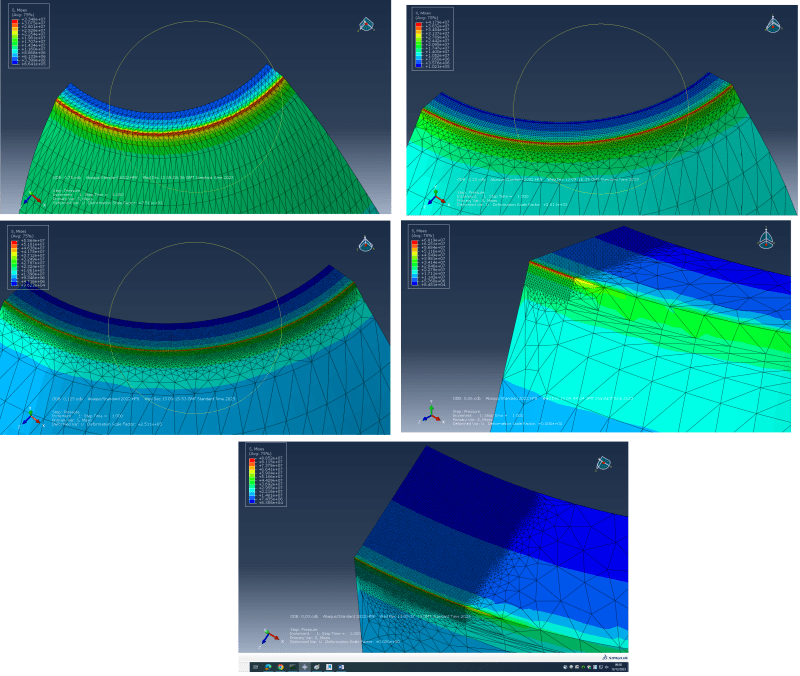
convergence_giy9es.png

Any help clearing this up would be greatly appreciated maybe it's correct but I'm just failing to interpret the results correctly?
Thanks
 
Replies continue below

Recommended for you

Let me guess, your constraint is along the red strip? So your infinitely stiff constraint is having to drive stress into the model to react the loads, and the smaller you make the elephants, the bigger the stress is. Model the compliance of the structure it is mounted to, et voila. In general it is often wise to model the test rig as well as the component.

Cheers

Greg Locock


New here? Try reading these, they might help FAQ731-376
 
Why didn't you model it as an axisymmetric part ? Or at least using cyclic symmetry ?

Is plasticity included ? Such sharp edges result in spurious stress concentrations and one way to make them more realistic is to include plasticity. Some small fillet would also help.
 
I've got it fully constrained on the whole of the top surface, cos its a de Laval nozzle but I've just modelled the diverging part of it. Is this the wrong way to do it? and i dont have a structure this is theoretical just for a final year university project, so i dont have a whole rig im more just modelling the effect of stagnation pressure on the nozzle
 
"I've got it fully constrained on the whole of the top surface, cos its a de Laval nozzle but I've just modelled the diverging part of it. Is this the wrong way to do it?"

Yes, that is wrong. You need to allow the nozzle material to expand radially and tangentially under the pressure load, while the surface reacts the axial load. There is also going to be some bending moments around the z-theta and z-r directions, where the nozzle meets the converging section, i.e. what Greg was saying about allowing for compliance of whatever the nozzle attaches to.

"im more just modelling the effect of stagnation pressure on the nozzle"

That's also not correct, the nozzle will never see stagnation pressure during operation, just static pressure...unless the outlet is plugged, which is a case only applicable for leak testing, which is not typically done at full stagnation pressure for the nozzle.
 
is the problem the red band ? can you show your constraints ? If axisymmetric, maybe you need cylindrical co-ord for constraints.

Rigid constraints are "deadly" for models, particularly if you're looking at stress. I'd probably support the model with finite stiffness constraints ... I'd support the model with dummy beams with some stiffness (like 10^4 or 10^7) and constrain the far end on the beams. The radial stiffness more need careful tuning, to match your symmetric constraint (on the sides).

Is your mesh detailing zone being affected by the symmetric constraint ? maybe detail a portion of the model, in the middle of your segment ?

"Hoffen wir mal, dass alles gut geht !"
General Paulus, Nov 1942, outside Stalingrad after the launch of Operation Uranus.
 
yes sorry i did mean static pressure that's the one i did, ive also changed it to axissymmetric instead of 3D now, so would the only constraint by on the y axis so it cant move up into the rest of the nozzle?
 
I'm away from my laptop now but can send the constraints tomorrow, i basically just did the top edge (previously surface when modelled 3D), where the throat would be and had it fully constrained in X,Y,Z. But i understand from btrueblood's comment about it needing to be able to expand outwards. Yes essentially the red band (which is a red point now i modelled it 2D axissymmetric) seems to be a singularity, when i refine my mesh the size of the part with high stress shrinks with it, so effectively if i made the mesh size 0.000000001 if the computer could handle it i would imagine i would have a single point nanometers in diameter with extremely high stress, which then skews the contour plots for the rest of the model. I will give the constraints a rejig to allow for radial expansion at the throat and update if that fixes the problem. I tried filleting it and adding plasticity as 'FEA WAY' suggested but it didnt seem to help. But what other people said in the thread makes sense now about about the infinitely stiff constraint forcing high stress on the edge
 
"made the mesh size 0.000000001" ... models with intergranular meshes are not more accurate.

But you have to apply some "common sense" to the model. If you're chasing a stress peak that may be due to some loading (a point load, a rigid constraint) then you're doomed to fail. Convergence is about is the model correctly representing the geometry. Are you looking at element centroidal stress or nodal averaged stress ?

Of more importance is the quality of the element mesh.

Do you have solid (3D) elements or 2D shells ?

Thermal effects may have more impact than pressure ?

Time dependent stress (like thermal effects over time) ?

Linear elastic (doomed to fail) or non-linear ??

"Hoffen wir mal, dass alles gut geht !"
General Paulus, Nov 1942, outside Stalingrad after the launch of Operation Uranus.
 
Often when there are artificial stress peaks at constraints or other model discontinuities, we simply ignore those areas and evaluate the rest of the model (and not bother with mesh refinement down to absurd sizes in a futile chase of a numerical singularity).
 
True, St Venant and all that, but I've had orribl surprises from ignoring the compliance of the rig/fixture/rest of the structure.

Cheers

Greg Locock


New here? Try reading these, they might help FAQ731-376
 
I can see problems with the structural boundary (with the "rest of the world") interacting with the axi-symmetric boundary. I'd rather model the full nozzle, and maybe investigate symmetry once I had the model running "believably".

"Hoffen wir mal, dass alles gut geht !"
General Paulus, Nov 1942, outside Stalingrad after the launch of Operation Uranus.
 
Status
Not open for further replies.

Part and Inventory Search

Sponsor