Eng-Tips is the largest engineering community on the Internet

Intelligent Work Forums for Engineering Professionals

FEA Nozzle Pressure Thrust 3

Status
Not open for further replies.

FPPE

Mechanical
Mar 4, 2022
162
0
0
IT
thread794-454328

Hello,

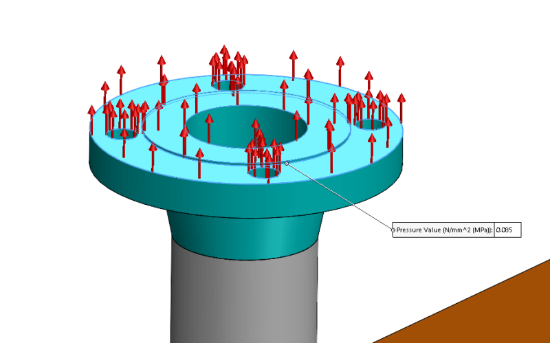
I refer to the article mentioned above: I would like to understand how (in formula) to calculate the pressure thrust to be inserted as traction pressure on the face of the flange.

Thank you
 
Replies continue below

Recommended for you

You don't add pressure thrust (PxA) as axial force to the face of flange unless you have un-tie expansion joint next to the nozzle or in line with the nozzle.
When pipe stress engineer doing flexibility analysis, they will add pressure thrust as needed to the piping system and to generate an equilibrium condition through the entire piping, such that the impact of the pressure thrust at the face of flange or at the vessel junction will be much less than PxA. and the local loads given by piping at the face of flange or at the junction already include the effect from the pressure thrust such that no need to add additional pressure thrust. Anyone still thinking to add pressure thrust is not thinking the entire piping system and overkill yourself. Check with your pipe stress engineer. What I have said above is also published in the category of a US expansion joint supplier (forgot the name) that demonstrates basic concept on nozzle loading with pressure thrust.
If anyone still thinks to add pressure thrust, then why not using WRC107 to check a 24"-150# manway with pressure thrust in a thin wall vessel. Guarantee failure.
 
The pressure traction is equal to the force from the internal pressure divided by the cross-sectional area that you are applying the pressure to. So, if you have just a simple pipe, the force from the internal pressure would be P*π*r[sub]i[/sub][sup]2[/sup]. The cross-section area that you would be applying the force to would be π*(r[sub]o[/sub][sup]2[/sup]-r[sub]i[/sub][sup]2[/sup]). When you divide the first by the second, the π's cancel out, leaving P*r[sub]i[/sub][sup]2[/sup]/(r[sub]o[/sub][sup]2[/sup]-r[sub]i[/sub][sup]2[/sup]).
 
In the attached image there is the area on which I applied the traction pressure thrust.

pthrust_kfrrr4.png


Do=190.39 mm
Di=74.64 mm
P=0.471 MPa
Pthrust=0.085 MPa

Is it correct to apply the pressure on the selected faces shown in the image?
Thank you
 
Are you following the rules in 5.2.2.5, 5.2.3.6, or 5.2.4.5? And if you are using 5.2.2.5, are you only calculating P[sub]m[/sub], noting that there are no limits on P[sub]L[/sub]?
 
I'm following the rules in 5.2.2.5. Yes I noted that it is necessary to calculate only primary membrane stresses.

You pointed this out to me because pressure thrust generates secondary stresses? So in theory I should not consider it in hydrotest condition?
 
It is necessary only to calculate the Primary General Membrane stress (P[sub]m[/sub]), and not even the Primary Local Membrane Stress, and compare it to the limit in 4.1.6.2. If you have Primary Bending, then you will also calculate that, and compare it to the limit in 4.1.6.2.

However, in almost every situation, P[sub]m[/sub] is a hand-calc, so you will not likely use FEA for that.

And yes, internal pressure and pressure thrust will indeed generate secondary stresses, which have no limit when considering the test condition. Secondary stresses also have no limit when considering the failure mode of Protection Against Plastic Collapse, either.
 
Status
Not open for further replies.
Back
Top