Rizkyffq
Mechanical
- Jun 5, 2017
- 53
Hello all,
So i am on project to create static simulation of radial stress inside a pipe but i got little obstacle on this project due i am kinda newbie on static simulation using Solidworks.
Probably someone that expertise on solidworks static simulation may help me.
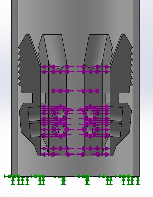
As picture above there 6 components that will generates radial stress (purple colour) to inside diameter of pipe.
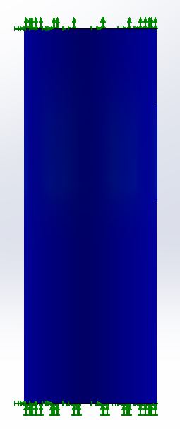
I already set the fixture for the pipe at above and bottom with fixed geometry (green colour). So assume that pipe is really fixed, only 6 components that generates radial stress to surface of inside diameter.
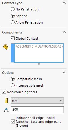
That is schematic of phenomenon that i desired, it seems simple but for many times i tried to run this simulation always failed, maybe i have mistaken to set the connector ?
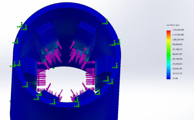
So the final result that i want maybe will become like this:
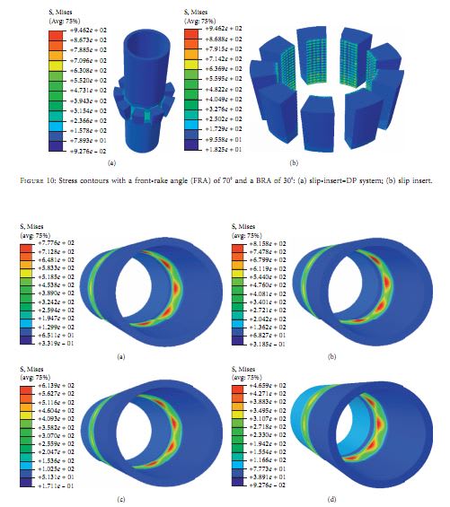
the different it just, radial stress came from the outside of pipe while in my case the radial stress come from the inside.
Hopefully someone that expertise in solidwork static simulation may help me for this case.
Thanks in advance sirs.
So i am on project to create static simulation of radial stress inside a pipe but i got little obstacle on this project due i am kinda newbie on static simulation using Solidworks.
Probably someone that expertise on solidworks static simulation may help me.

As picture above there 6 components that will generates radial stress (purple colour) to inside diameter of pipe.
I already set the fixture for the pipe at above and bottom with fixed geometry (green colour). So assume that pipe is really fixed, only 6 components that generates radial stress to surface of inside diameter.
That is schematic of phenomenon that i desired, it seems simple but for many times i tried to run this simulation always failed, maybe i have mistaken to set the connector ?
So the final result that i want maybe will become like this:

the different it just, radial stress came from the outside of pipe while in my case the radial stress come from the inside.
Hopefully someone that expertise in solidwork static simulation may help me for this case.
Thanks in advance sirs.

