Eng-Tips is the largest engineering community on the Internet

Intelligent Work Forums for Engineering Professionals

FEA - stresses in bolt. How to interprete?

Status
Not open for further replies.

RayJohnson2

Mechanical
Jun 22, 2015
32
0
0
BE
I am designing some components that are subject to forces and pressures. So I need to calculate and check if the strength of these components is okay to be safe.
I am doing this by Finite Element Analysis (FEA) in Creo Parametric (Simulate module).

Doing FEA is one thing. Interpreting the results is another. You always have peak stresses that occur locally. And I find it difficult to assess how 'bad' this is and how high the peak stresses can be before they become a safety risk.

Therefore I decided to model a stainless steel M12 bolt. Because I know the recommended maximal load for this. Looking at the peak stresses that I find on my FEA of this bolt might teach me something to interprete occurring stresses on my other models.

Data: component is a metric M12 bolt (nominal diameter = 12 mm, thread pitch = 1.75 mm).
Material: Stainless steel A2 50.
Max load for M12 in A2 50: 17 700 N
0.2% yield strength of SS: 215 MPa (N/mm^2^)
Ultimate strength of SS: 510 MPa (N/mm^2^)

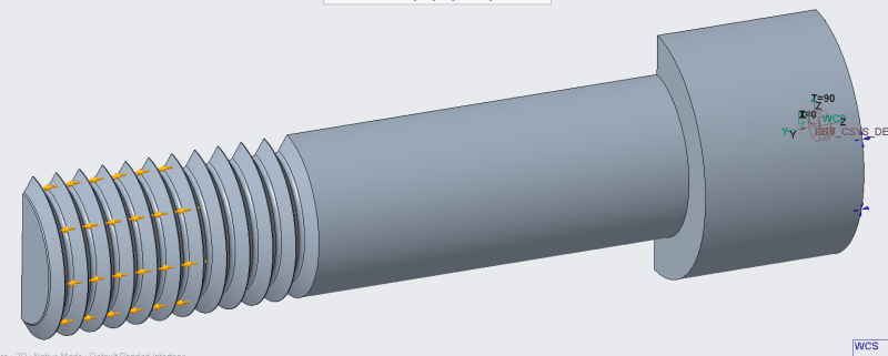
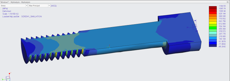
The screwthread I modeled, not as a spiral, but as circular grooves.
I cut the model in half to apply a symmetry constraint and to be able to 'look inside' the material.
I applied a force of 17 700 N, divided by 2 because I only use half a model.
This force I applied on the flanks of the thread grooves, over a length of around 10 mm. 10 mm is the thickness of a M12 nut.
I applied a displacement = 0 constraint on the top of the bolt head. The bolt is long enough, so that constraint should not influence the stresses in the thread area.

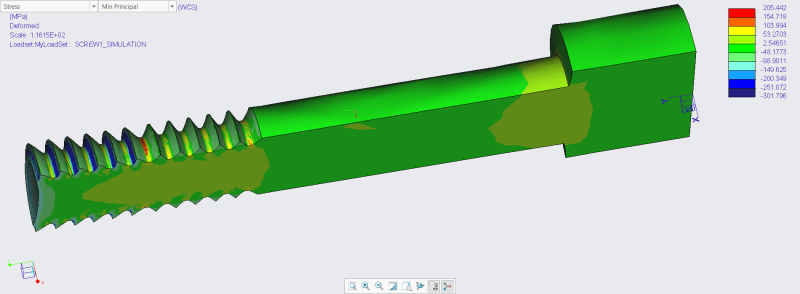
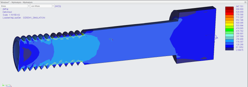
I then checked Von Mises, Max principal and Min principal stresses.
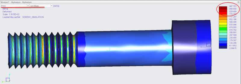
VM max stress: 947 MPa
Max principal stress peak: 1164 MPa
Min principal stress : -300 to +205 MPa

The stress peaks are higher than the ultimate strength of 510 MPa.
Clearly, M12 bolts can be used in this condition. So how should I interprete these results?
Can I simply ignore the stress peaks, as long as they are small enough?
When can a stress peak become a problem?

m12_5_beech0.png
m12_3_tkuzl2.png
m12_1_kinwrx.png
m12_2_b8chhk.png
m12_4_ioyur6.png
 
Replies continue below

Recommended for you

Why would you model a bolt??
Bolts have tensile and shear strengths provided in the associated parts standard or vendor datasheet. Just use those values.
 
SWComposites said:
Why would you model a bolt??
Sorry if my explanation in my first post wasn't clear enough.

I used a bolt to model and calculate stresses because it is a 'known safe' component, if you don't apply larger than allowed loads.
Knowing this, I wanted to see what (peak) stresses appear in my simulation of the bolt and how they relate to the 0.2% yield strength and the ultimate (rupture) strength of the material.
I want to learn from this, to get an idea of what peak stresses I can accept in the other components that I am designing and modeling.
I hope this clarifies my intentions.
 
Ok, that makes me feel a bit better.
But bolts have a highly complex stress state, and its going to be hard to correlate predictions to actual bolt strength test data.
And every bolt has a small fillet between the head and shank, which you will need to model to get somewhat accurate stresses in that area.
Now re stress peaks, if you are applying the bolt ultimate tensile load, and predicting higher stresses than the material Ftu allowable, then you need to account for plasticity. There is no practical way to say "a peak stress area of XXX" or a "peak stress value of YYY" is acceptable. You need to correlate the FEM, with non-linear effects are required, so that you can predict the actual bolt strength. Then you can (sort of) apply the same modelling approach, for the same material system, to other parts.

 
Yes, you are right.
A bolt has a complex stress pattern when loaded.
But it was the only mechanical component I could think of that has both a known and defined shape, and a known maximum mechanical load. That's why I wanted to see what that gives as 'results' when simulating this by FEA.

If anyone can think of a more simple mechanical component that also has defined shape and specified max load, please let me know. Would be an interesting exercise to try to simulate that also.

 
The red stress is all "on the surface" - there is no depth to it. That's a good indication that what you are seeing is an artifact of the analysis.

Things that could cause this include:
The boundary conditions of your load application.
Deflection of your "threads", which are unsupported by the nut in your model vs. reality where they would be supported.
The geometry of the thread profile.
The size and shape of the mesh.
The stress gradient between adjacent elements.

If you want to take away some of those factors, try a similar analysis with a long rod with a circumferential notch in the middle. With a long rod, with forces and reactions applied at the ends you can eliminate the load application from the area of interest.

Play with notch geometry. Play with mesh.
 
"The red stress is all on the surface - there is no depth to it."
- Yes, I noticed that too, but I thought maybe that stress on the surface is enough to cause small local ruptures and initiate cracks, that might increase in size?

"Deflection of your "threads", which are unsupported by the nut in your model vs. reality where they would be supported."
- That is definitely a factor. My FEA software (Creo Parametric) can handle such simulations, where 2 or more parts interact with each other. Unfortunately, I don't have the required license for that. So I tried the 'next best option'.

I played with mesh size, not (yet) with the shape of mesh elements.
I might try your suggestion (the long rod).
Thanks!

 
"maybe that stress on the surface is enough to cause small local ruptures and initiate cracks, that might increase in size"

True torque to yield fasteners removed after installation often are .001" or .002" longer than before torquing. And when relaxed probably contain residual compressive stress in the very areas/regions that were highest tensile when installed.
Yielding and material elongation properties are almost 10% even on US grade 8 or metric 10.9 bolts.

A controlled initial overstress can leave a component in actual real life service with reduced tensile or even beneficial compressive stresses in the very locations that showed red on the post processing renderings and print outs.
Hence others' comments about the necessity of non-linear analysis the moment the discussion escalates beyond yield stress.

 
Creo Simulate has a fastener feature - use it. Modeling threads is chasing the near-impossible.

I agree with the others - if you're applying a preload that is proven to be robust in the real-world, there's not much else to learn here. (I had a colleague who insisted that bolts could not be torqued past the minimum compressive yield of the base metals - on paper it's possible - but in the real world, torque and preload specs routinely exceed that "limit" and we never saw impressions in used components. Moral of the story - there's a lot going on and testing / experience is worth more than some tiny spots of red on an FEA.)

Creo Simulate has some basic nonlinear modeling capabilities but plasticity is not one of them. It would be nice, to see if plasticity causes the hot spots to dissipate.

Feel free to drive up the mesh resolution or polynomial orders in Simulate. In my experience the little red spots will move around and maybe get smaller but they won't vanish.
 
I didn't know that Creo Simulate had a Fastener feature. I looked for it but the toolbar icon is greyed out. So probably my Creo license doesn't cover that feature.

I did drive up the mesh resolution and polynomial orders in Simulate.
But that indeed doesn't bring much improvement.

Yes, I am beginning to see that my goal of 'running simulations on a known component to get an idea of acceptable (peak) stresses' wasn't the best idea to begin with.

Thanks for your input!
 
The easiest way to get some experience with FEA is by starting very simple from the basics. Start by analyzing a rod that is fixed on 1 end and has a force on the other end. Check to see if the stresses equal F/A. Increase the complexity by adding a notch for which you can calculate the stress concentrations. Build on that by simulating more complex parts for which you can still verify the stresses by hand. You can basically go through all the different cases that you've been thought to solve by hand in uni.

It also helps to learn a standard that prescribes how the stresses (from FEA or from other methods) should be further analyzed to see if they are acceptable or not. 1 such a standard is the FKM guideline, which can be used for both a static analysis (e.g. against overloads) and a fatigue analysis. I'm from the EU so they might use other guidelines in the US.
 
Status
Not open for further replies.
Back
Top