RayJohnson2
Mechanical
I am designing some components that are subject to forces and pressures. So I need to calculate and check if the strength of these components is okay to be safe.
I am doing this by Finite Element Analysis (FEA) in Creo Parametric (Simulate module).
Doing FEA is one thing. Interpreting the results is another. You always have peak stresses that occur locally. And I find it difficult to assess how 'bad' this is and how high the peak stresses can be before they become a safety risk.
Therefore I decided to model a stainless steel M12 bolt. Because I know the recommended maximal load for this. Looking at the peak stresses that I find on my FEA of this bolt might teach me something to interprete occurring stresses on my other models.
Data: component is a metric M12 bolt (nominal diameter = 12 mm, thread pitch = 1.75 mm).
Material: Stainless steel A2 50.
Max load for M12 in A2 50: 17 700 N
0.2% yield strength of SS: 215 MPa (N/mm^2^)
Ultimate strength of SS: 510 MPa (N/mm^2^)
The screwthread I modeled, not as a spiral, but as circular grooves.
I cut the model in half to apply a symmetry constraint and to be able to 'look inside' the material.
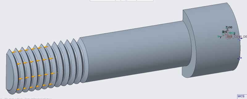
I applied a force of 17 700 N, divided by 2 because I only use half a model.
This force I applied on the flanks of the thread grooves, over a length of around 10 mm. 10 mm is the thickness of a M12 nut.
I applied a displacement = 0 constraint on the top of the bolt head. The bolt is long enough, so that constraint should not influence the stresses in the thread area.
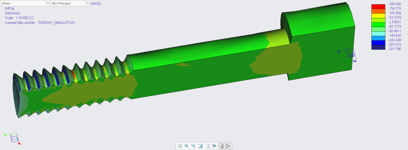
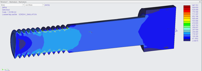
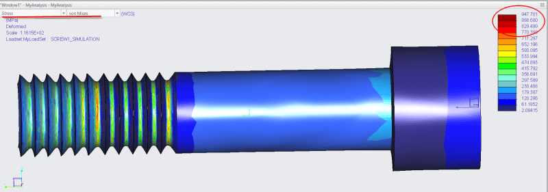
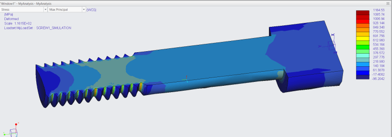
I then checked Von Mises, Max principal and Min principal stresses.
VM max stress: 947 MPa
Max principal stress peak: 1164 MPa
Min principal stress : -300 to +205 MPa
The stress peaks are higher than the ultimate strength of 510 MPa.
Clearly, M12 bolts can be used in this condition. So how should I interprete these results?
Can I simply ignore the stress peaks, as long as they are small enough?
When can a stress peak become a problem?


