Eng-Tips is the largest engineering community on the Internet

Intelligent Work Forums for Engineering Professionals

  • Congratulations waross on being selected by the Eng-Tips community for having the most helpful posts in the forums last week. Way to Go!

FEA vs Code/Roark calculation? 3

Status
Not open for further replies.

LearningENG-

Mechanical
Jan 17, 2020
25
CA
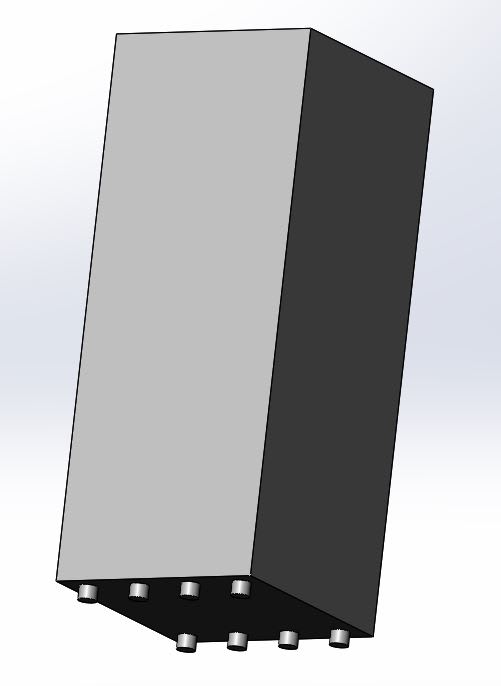
Hi I’m trying to verify in FEA my hand calculation of a rectangular chamber subjected to external pressure.

It's a chamber with rectangular cross section (see attached picture) whose inner dim. are 22"*24"*57.25". It has equal wall thickness of 0.75". The material is Aluminum 6061 T6 with a yield strength of 276 Mpa and Young's modulus of 68.9 Gpa. When running the simulation, I applied uniformly distributed external pressure of 101 kpa while fixing the bottom faces of the supporting feet. I applied shell elements for the walls and solid elements for the feet.

I'm currently comparing the bending stress between ASME VIII 13 and FEA (the normal stress in X & Z directions respectively, and Solidworks actually allows me to show "bending stress" for shell elements) and I got the following:

ASME results (compared with FEA):
Long side: SbN = 29.81 Mpa (93.01%); SbQ = 47.76 Mpa (120.97%)
Short side: SbM = 17.42 Mpa (79.29%); SbQ = 47.76 Mpa (120.97%)

While from FEA:
Long side: SbN = 32.05 Mpa; SbQ = 39.48 Mpa
Short side: SbM = 21.97 Mpa; SbQ = 39.77 Mpa

So it surprises me that there are 20% difference between FEA and ASME.
Capture_1_lvzred.jpg
Capture_2_u4vipd.jpg

Anyone has any insight on this?

Thanks
XS
 
Replies continue below

Recommended for you

You're going to need to provide a lot more information if you want assistance with this. And remember that pictures really help - especially when they have coordinate triads on them.
 
Hi TGS4,

Thank you for your reply. Yes you're right. I have updated the post.

I did figure out which stress to compared with in FEA but I'm not getting good results.

Regards
XS
 
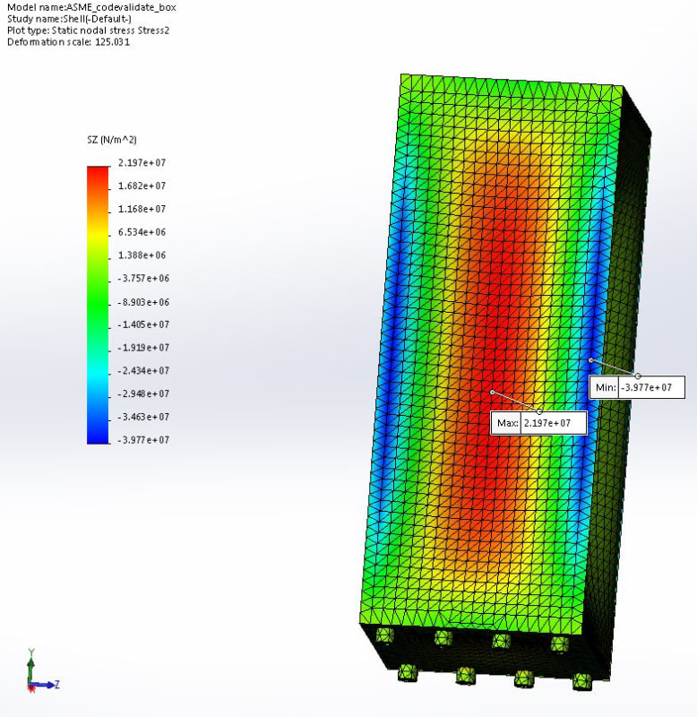
Can you post a figure showing your mesh overlaid? You can do this by going into the stress results settings and selecting "mesh" from the dropdown menu within.

Michael Hall, PE (TX) PMP - President
Engineering Design Services LLC
 
Hi Michael,

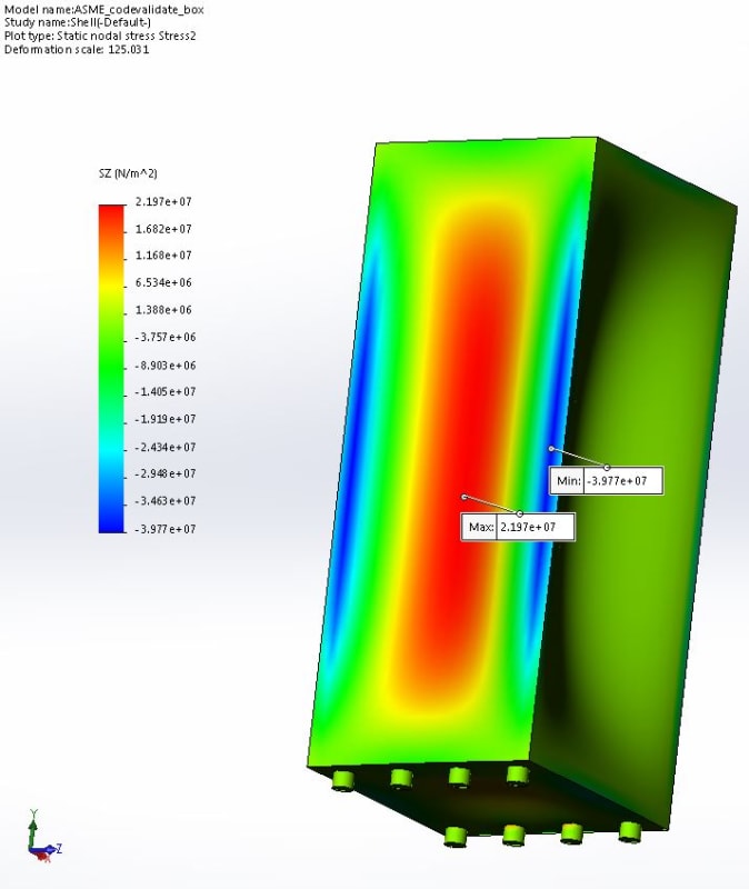
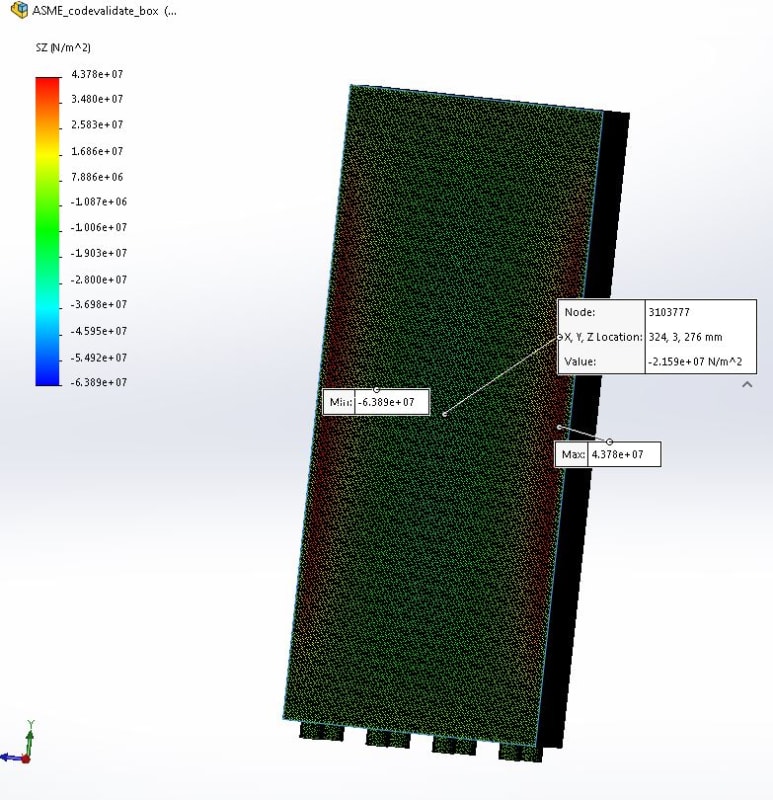
Please find the plots attached. Also I attached another result plot with solid mesh (I know it's too many elements but I just wanted to make sure there are 3 elements along the thickness and this is a simple geometry so I just mapped the whole thing with super fine meshes). I also don't understand why with the shell mesh I get only 39 Mpa for at the centre of the long edge while with the solid mesh I get more than 60 Mpa. Same thing happened when I was trying to only simulate a simple plate with 4 edges fixed.

Regards,
XS
Shellwmesh_uxgwrn.jpg
Solidwmesh_ckpray.jpg
 
I did a quick check of your model and got similar results. I would take care with sharp edges, though, as that may skew your results in a FEA simulation.

Which equation are you using specifically for calculating bending stress? I have no idea what you mean by "ASME VIII 13".

Michael Hall, PE (TX) PMP - President
Engineering Design Services LLC
 
Hi EngDesServices,

I did the calculation with ASME VIII DIV 1 appendix 13-7 (a),UNREINFORCED VESSELS OF RECTANGULAR CROSS SECTION.

Yes the biggest stress value appear at sharp corners, it's just I'm not sure in manufacturing how they would make the corners not sharp? To what degree should I fillet the corner to represent a real world fabrication?

Regards,
XS
 
Design calculations are not all that is necessary.
Think on fabrication details, welding, inspections, pressure test, etc., etc.

Regards


@LearningENG
13-4(h) stated that the design equations are based on vessels in which the length to side dimension is greater than 4...Short unreinforced or unstayed vessels...having an aspect ratio not greater than 2.0 may be designed in accordance with 13-18(b) and 13-18(c).

As for vessels of noncircular cross section subject to external pressure, you may use Appendix 13, 13-14.

About your FEA, try to run the "Pressure Vessel Design" moudle of SolidWorks Simulation and try to use the Linearization tool, this will help you to define Bending and Membrane stress.
 
Thank you all for your replies.

So now I'm applying chambers to the chamber of 6mm (represents the weld fillet) to see what I can get from it..

r6155, Yes that is a very good point, but I just want to at lease make sure the design is not too off by simulation. I don't really have much experience in the real fabrication conditions yet :(

IdanPV, yes but my chamber is actually greater than 2 (2.5 to be exact), and I think the code also says for ratios less than 4 the design guide can also be used for conservative design. And yes, 13-14 is what I am using. The "pressure vessel design" is something I will definitely look into, thank you for the tips!!!

Regards,
XS
 
ASME results are clearly for an infinitely long vessel, as this condition is conservative; however, with an aspect ratio of nearly 2.4, the stresses are very close to the infinite case.
As you have the long side length close to the short one, one can calculate the sides as clamped plates: the common formulae for this (and for your aspect ratio) give something close to 52 MPa for the bending stress at the corner of the long side. To get closer with an estimate, we can calculate the stress for the short side and take the average stress between the two sides. The stress for the (clamped) short side is close to 44 Mpa, so the estimate for your condition would be 48 MPa.
My conclusion is that ASME values are the correct ones, and you should review your model. With shell elements you should get results much closer to the theoretical ones, as these are based on the same theoretical basis.

prex
[URL unfurl="true"]http://www.xcalcs.com[/url] : Online engineering calculations
[URL unfurl="true"]https://www.megamag.it[/url] : Magnetic brakes and launchers for fun rides
[URL unfurl="true"]https://www.levitans.com[/url] : Air bearing pads
 
Hi Prex,

Thanks for your reply. Do you have any suggestion on how to improve the model? It's a really simply model and I don't have much clue on how I should improve it...

regards,
XS
 
@LearningENG,
There are few things you can do.
1. You can model only 1/4 of the vessel and use the symmetry restraint on the section plane. This will give you the option to use finer solid mesh.
2. As I said, try yo use the "Pressure Vessel Design" and the linearization tool of SolidWorks.
 
The closed ends will produce a 5-10% error. Either double the length of the vessel or remove the closed ends.

You could make a quarter model with symmetry as IdanPV suugests.

Using shell elements should mean you avoid linearising and acheive accurate results.

The simplest FEA would be make it a 2D model (a crossection of the quarter model) using 1D beam elements and use Plane strain to simulate infinite length.
 
LearningENG,
you should take care of representing as close as possible your geometry. To do so, the shell flat elements should lie in the middle plane of the wall. However this will increase the pressure loading, and it is up to you to decide whether to maintain the design pressure (conservative) or to reduce the calculation pressure in order to maintain the same total load.
I don't think that the vessel length with the position of the flat ends has much influence on the stresses at mid length.
If you still find those high discrepancies, you should try a clamped flat plate representing one face of the vessel: for this case there is ample literature (e.g. Roark), so you can directly compare FEA with anlytical results (and you should get a very close fit).

prex
[URL unfurl="true"]http://www.xcalcs.com[/url] : Online engineering calculations
[URL unfurl="true"]https://www.megamag.it[/url] : Magnetic brakes and launchers for fun rides
[URL unfurl="true"]https://www.levitans.com[/url] : Air bearing pads
 
It looks like SbQ in your shell model might not be fully converged. Did you try refining your mesh to see if you get the same result? You're going from 24 MPa to 40 MPa across one element.

When you report Sz, is this the bending component only or the bending plus membrane stress? The membrane stress will push your FEA results toward the ASME results in both areas.

Prex's point about modeling shell elements at the mid-plane is a good one, including the effect this has on the pressure load. I would not recommend decreasing the pressure to keep the same total load, though, because it is the moment that you need to match. Just to see how big of an effect this is, you can reduce the thickness and see if ASME and FEA are closer to one another. Or bound it by re-modeling with the shell's at the inside surface (although this is not a recommended practice in general). I would not expect this to cause an error more than ((H-t)/H)^2.

I'll second the use of symmetry and also looking at the sensitivity to length, which were mentioned by others. From your contour plots, SbQ does not look like it will be independent of length, at least not at the level of accuracy you are looking for.

-mskds545
 
Status
Not open for further replies.

Part and Inventory Search

Sponsor

Back
Top