Continue to Site

Eng-Tips is the largest engineering community on the Internet

Intelligent Work Forums for Engineering Professionals

  • Congratulations Toost on being selected by the Eng-Tips community for having the most helpful posts in the forums last week. Way to Go!

FEA_PIPE SUPPORT ( 3 BOLT CLAMP)

Status
Not open for further replies.

FEA_SJ

Mechanical
Dec 19, 2019
5
Hi,

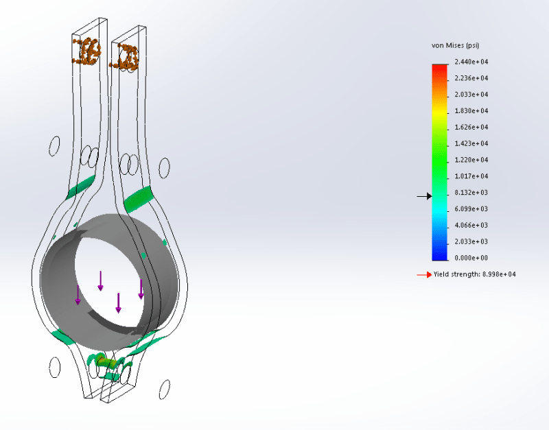
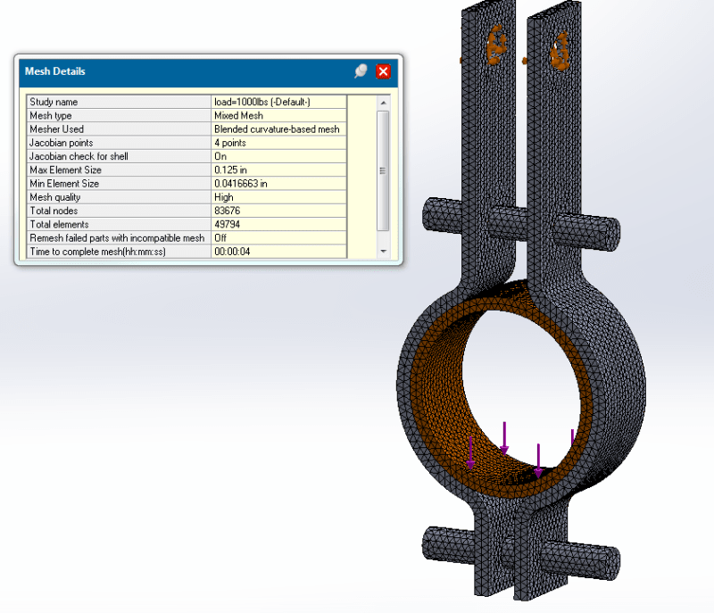
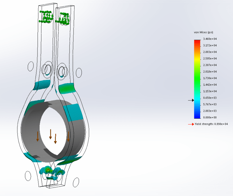
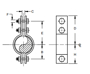
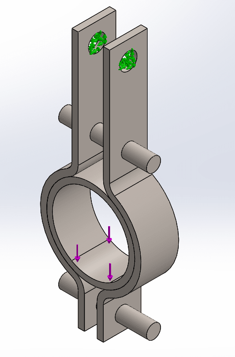
I am trying to conduct a load analysis for a 3 Bolt Clamp. I would like to get your thoughts on how to set up my model for analysis. The way I have it set up is: The top bolt hole is fixed and the load is on the pipe at the 60-degree bearing surface. The pipe is set to be rigid. There is no penetration contact between the pipe and the clamp. In this case, the pipe size is 3". The load is 1000 lbs @ 1000deg F. The max allowable stress as per MSS SP58 @ 1000 deg is 8KSI for A3875. The stock size is 1/4" X 1-1/4". Please if anyone could verify this setup for accuracy or have any other ideas on how to improvise on it, that would be great.

Based on my set up the stress value is coming out to be way above the allowable. This should not be the case as we have been using these clamps in the field for a very long time without any issues.


304_z627vn.png
Capture2_ctsssj.png
 
Replies continue below

Recommended for you

Can you attach a picture showing mesh and results ? Be careful when meshing in SolidWorks Simulation (I recognized that you use this software based on the second picture). This program tends to generate very coarse meshes that almost always require global and local refinement.

Which contact do you use for bolt-clamp interface ? If bonded then try with no separation. Also I would rather model this pipe as deformable. It’s a fairly simple model so this shouldn’t affect the performance of computations too much.

Finally, include geometric and material nonlinearity in the analysis to increase reliability of results.
 
Here are the pictures for my result and mesh details. Thanks!

1_hdcn0u.png
1_a9svfq.png
 
I tend to mesh in such a way that I have at least two elements/thickness of the shortest edge. I used blended curve mesh which I believe gives better results.
For contact, I used a global contact bonded for bolt clamp contacts.

Also, you stated to use geometric and material nonlinearity. I have never used it before. Could you please let me know a little bit more about it. I appreciate your feedback. Thanks!
 
surprised that the pipe is gapping at the top of the clamp. Yes, understand the load is down.

Is there a support element between the upper "tangs" (getting squeezed by the clamping) ?

TET10s ?

Is 1000 lbs a typical load, or just a convenient number ?

What's the stress pic without load (ie due to the installation clamp up) ?

Is yield 9000 MPa (like your pointer in the scale) or 90000 MPa (as written) ?

You say you're running with material non-linearity, but getting stresses in excess of yield ?? Maybe the clamp plate is material non-linear, but not the bolt ?
The contact loading at the lower bolt looks suspicious … too concentrated ??

another day in paradise, or is paradise one day closer ?
 
1000 lbs is something we have used for these clamps.

There is usually a spacer between the two half clamps at the lower bolt location on the top ear.

8 KSI is the yield as per the code we use. Ignore the one that the marker shows.

I am not using any non-linearity option for this study.
 
The mesh looks good. I would recommend at least 3 elements per thickness though.

Try solving this with material nonlinearity. Use basic von Mises bilinear plasticity model available in SW Simulation for this purpose. You will have to specify additional data for this model - yield strength, tangent modulus and hardening factor (proportion of kinematic and isotropic hardening). You can assume tangent modulus value as 10% of Young's modulus and specify hardening factor equal to 0 (pure isotropic hardening). When you introduce plasticity to your analysis, the results may become much more valuable.
 
Such a clamp is intended to yield when clamped. It will not be the same shape after it has been tightened once.
 
I'm alittle surprised that there isn't some spacer between the clamp plates, to limit the squeeze.

Of course the counter is that these very simple clamps are intended to be used with sturdy pipes.

another day in paradise, or is paradise one day closer ?
 
@rb1957: As I mentioned earlier, there is a spacer between the two halves. Please see the attached results.


1_b1jhqf.png
1_xjfkdp.png
 
Status
Not open for further replies.

Part and Inventory Search

Sponsor