Eng-Tips is the largest engineering community on the Internet

Intelligent Work Forums for Engineering Professionals

Feature Control Frame with Multiple Leaders (Angularity) 1

Status
Not open for further replies.

Ben K

Mechanical
Aug 20, 2024
3
0
0
US
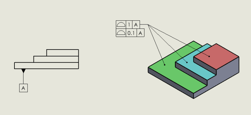
We have a customer who has put a feature control frame with multiple leaders, pointing to 3 parallel planes. The feature control frame has 3 leaders, pointing to the 3 planes. The tolerance in the feature control frame is an angularity tolerance. It is my understanding that the 3 planes should be treated as one feature, which should be aligned with the datum within the specified tolerance. Is this correct?
Can anyone point me towards some literature on this subject? I haven't figured out a way to measure this with my CMM (Verisurf) - maybe if I know the correct verbiage for this scenario google with help me find a way to do it in Verisurf. (See attached example)
 
 https://files.engineering.com/getfile.aspx?folder=108151a2-835d-450f-b36c-e7873b0cf2d8&file=Screenshot_2024-08-20_100554.png
Replies continue below

Recommended for you

The callout is fine, but it doesn't mean they are treated as one feature. Instead, each of those 3 surfaces is measured for angularity back to datum A. Unless there's a weird angle that we can't see, it seems to be identical with using parallelism on those 3 surfaces.
If you swap parallelism in there rather than angularity, would that make it easier to handle on your Verisurf?
 
The customer's intention is to treat them as one feature. They are mounting a device with 3 mounting points, on those 3 planes, and the angle of that device relative to Datum A is critical. Treating each plane as it's own feature, or just using a surface profile would result in an unnecessarily tight tolerance (the position of the group of planes relative to Datum A is of little consequence, only the angle is critical).

So maybe the revised question is how should the customer call this out on their drawing to convey their intent?

The screenshot I attached is just a simplified demonstration to protect our customer's IP, but the concept is the same. Parallelism and Angularity are the same, parallelism is just an angle of zero.
 
" It is my understanding that the 3 planes should be treated as one feature, which should be aligned with the datum within the specified tolerance. Is this correct?"

It is not correct. There is no simultaneous requirement for angularity or any other orientation geometric characteristic tolerance.

If they need to move together use a profile geometric characteristic tolerance. This does allow for a simultaneous condition. You may use a larger tolerance for the entire group and then a smaller tolerance for variation within the group using a composite tolerance symbol. If both levels of the composite symbol refer to datum feature A, then the top will allow vertical motion as well as orientation change; the lower one will limit orientation with respect to datum feature A as well as to each other.
 
Screenshot_2024-08-20_121348_izhfuy.png


Thanks for the reply. Ok, so if I'm understanding you correctly, if I set up my composite profile as shown in the this updated screenshot, each individual plane would have to fall within 1mm of basic with respect to A, and then as a group, their orientation relative to A must be within 0.1mm. Am I understanding that correctly?
 
I agree with Garland23 and 3DDave (and jassco). The fact is that they are 3 separate surfaces, even if they are serving 1 function. The manufacturing process will inherently have variation between the steps, and the GD&T is necessarily specifying the max allowable variation among them.
 
Status
Not open for further replies.
Back
Top