Continue to Site

Eng-Tips is the largest engineering community on the Internet

Intelligent Work Forums for Engineering Professionals

  • Congratulations KootK on being selected by the Eng-Tips community for having the most helpful posts in the forums last week. Way to Go!

Feature of Size

Status
Not open for further replies.

dthom0425

Mechanical
Dec 6, 2018
46
Hi all,

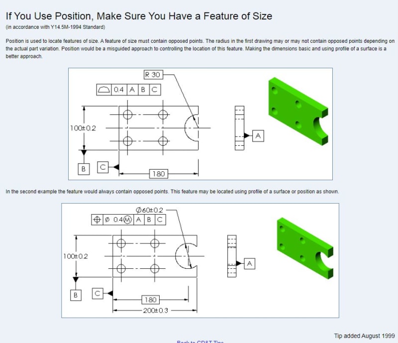
Let's say you have a thick plate, and on the edge of the plate you cut a blind hole so the center of the hole is coincident with the edge of the plate. You end up with a semi circle cut...basically an open ended hole.

Can a positional tolerance apply to this type of feature or is profile the more correct control?

Thanks for the help
 
Replies continue below

Recommended for you

This comes from the Tec-Ease tip published in August 1999:

snappy_ve4ydv.jpg
 
Not sure that I agree with the second statement in their tip.
The general idea is correct, but "always contain opposed points"? No.

John-Paul Belanger
Certified Sr. GD&T Professional
Geometric Learning Systems
 
If you follow textbooks etc this is generally considered a non-FOS feature. Purely per the ASME Y14.5 standard, there could be different (opposing) arguments made depending on how one interprets the muddy parts of it.
Practically I don't think there would be an issue if the tolerance is applied at MMC.
 
Appreciate the responses.
I guess I'm still left wondering why the slightly extended hole (bottom picture) is OK for positional tol per Tec-ease versus the top picture. Is position not OK in the top picture because there's an opportunity for the form to allow a feature that is slightly less then a semi circle (therefore, you wouldn't have opposed points to form at least half your circle). Is position OK in the bottom picture for the exact opposite reason (the slightly extended hole gives you opposed points up to at least the semi circle to generate a circular element)?
Grasping at straws

Thanks for the help again
 
dthom0425,

The wording of the standard technically require that position and some other controls require that for most practical purposes the feature be defined as a Feature of Size (FOS) - there is some wiggle room for possibly bending these rules with the application of MMC as it does not involve a UAME as Burunduk suggested, but that is a whole other topic. Assuming you are going by ASME Y14.5 the subject of FOS vs nonFOS can bring up significant debate - a search around these forums will bring up a plethora of discussions on the topic.

The main defining feature of a FOS not directly covered by the definition for regular FOS (regular FOS is a fully formed cylinder, opposed parallel planes, etc..) is whether it can be contained or contained by a Unrelated Actual Mating Envelope (UAME). What exactly this means can again be the subject of debate, but for practical purposes in your example your UAME would be a theoretical cylinder expanded within the half cylinder not constrained to any datum features. Imagine using an expanding pin which is not fixed in location/orientation (free floating) which is expanded within the feature for both cases (cylinder having less than 180 deg and cylinder having more than 180 deg) - is there a point at which the feature limits expansion of the pin? I would answer no to the less than 180 degree case and yes to the more than 180 degree case - some others may have differing opinions but I find this to be the most useful interpretation.
 
This is a case where desirable parts will be acceptable, but the partial encompassment allows far more mobility to the feature boundary than can be explained by a change in the diameter, accepting parts that are unexpected. Curve fitting on a CMM can be used to extrapolate, but the use of gauges cannot.
 
Status
Not open for further replies.

Part and Inventory Search

Sponsor