Eng-Tips is the largest engineering community on the Internet

Intelligent Work Forums for Engineering Professionals

Feature qty vs centerline 1

Status
Not open for further replies.

mackra

Mechanical
Sep 7, 2011
16
0
1
US
Hi,
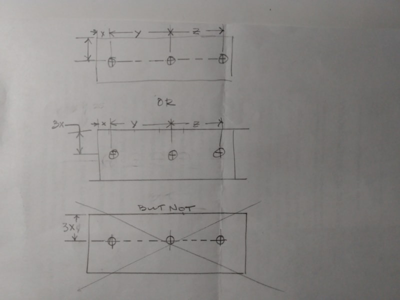
Pretty fundamental/basic question, but I'm not finding a reference for the "standard" or best practice statement. I consider it to be double dimensioning if the quantity and centerlines are used simultaneously. Referring the the crude sketch below, the usage of centerlines OR quantity callout is permissible, but not both. What's the 14.X or best practice statement stating such?
Thanks,

IMG_20240213_170914543_h7kqd2.jpg
 
Replies continue below

Recommended for you

It's fundamentally wrong. You should put 3X to the hole dimension, not the locating dimension.
Using the centerline gives the information that the holes lie on a common plane X distance from the side.
 
Is there a mating part with 3 holes?
How is that dimensioned ?

Will "basic" dimensions and "true position" tolerancing be used?
 
The closest that I had found is from ASM Y14.5 2018, pg 31 , fig 4-15.

2024-02-15_05-04_mtuvn0.png


In that figure with y axis is vertical, x axis is horizontal, the part's centerline and hole centers are coincident. Assume in my example that is not the case. Figure 4-15 doesn't address the case in my sketch and quantity callout convention. At a previous employer during a drawing review I made the double dimensioning mistake, but I can't recall what the checker cited, if it was an AMSE reference or what. It almost seems like it could have been a military reference...I just can't recall.

I'm now reviewing drawings, the double dimensioning similar to my initial post is commonly done, which I am attempting to end. But I want to reference a standard or good engineering practice, and not a "preference" if that makes sense.
 
It's not fundamentally wrong to indicate the number of places that a location dimension takes place. Although The standard doesn't show that for true position dimensions for round holes, it does show it for true profile locating dimensions for irregular shaped holes.

This is from ASME Y14.5-2009:
Screenshot_20240215_162253_Drive_cp7x5d.jpg
 
The 3rd image I would do only if there was an overall dim of the part, and the hole horiz CL goes thru the part. It would be inferred the holes are at the center of the part.
Otherwise I would go with the 1st image.

Chris, CSWP
SolidWorks
ctophers home
 

Tmoose (Mechanical)
14 Feb 24 13:09
Is there a mating part with 3 holes?

Could be two parts, one part using one hole, the second part using the other two.


How is that dimensioned ?
Will "basic" dimensions and "true position" tolerancing be used?

This is not really a GD&T question, just a general practice question. For this print and my employer we don't use GD&T. I meant to take a screen shot of the drawing. The drawing is in general not very tidy due to the amount of centerlines used and then those centerlines having quantities callout. Very cluttered.
 

Wuzhee (Automotive)
14 Feb 24 07:17
It's fundamentally wrong. You should put 3X to the hole dimension, not the locating dimension.
Using the centerline gives the information that the holes lie on a common plane X distance from the side.


The locating dimension is common, the hole diameters may not be.
 

Eric Gushiken (Mechanical)
15 Feb 24 06:36
The first and second example are both fine. The 3rd one is redundant but still understandable. It's not a big deal and I wouldn't necessarily say it's wrong.

The "standard" or good practice statement was very clear that both are not to be used, doing so was double dimensioning. The reference was not a a company document/policy.
 
I came across this a few minutes ago. It wasn't a hit when I initially searched. The difference being I've included the use of quantity and the common centerline.
thread1103-401582
 
Status
Not open for further replies.
Back
Top