Continue to Site

Eng-Tips is the largest engineering community on the Internet

Intelligent Work Forums for Engineering Professionals

  • Congratulations KootK on being selected by the Eng-Tips community for having the most helpful posts in the forums last week. Way to Go!

Features you wish NX had? 32

Status
Not open for further replies.

junfanbl

Marine/Ocean
Jun 10, 2015
90
Hello, I am curious to know peoples opinions on what they like most about NX and some new features( or improvements) that it could use. I know I can think of some myself. I ask because I am always trying to gather ideas on how to better utilize the software in my own personal workflow. Part of that for me is developing scripts and stand alone libraries that extend NX functionality.

So I thought what better way to get ideas than to ask the engineering community in general. Your thoughts are appreciated.

 
Replies continue below

Recommended for you

I'm using components. It's just that components contain only WAVE-linked copy of a body, rather than the feature tree. The actual feature tree is contained elsewhere. At any rate, that is one of the implementations, and Top-Down has many. After all, we are talking about NX and our freedom of choice is remarkable.

 
Keeping the full feature tree of multiple parts at the assembly level in a single file may quickly turn into a maintenance and documentation control headache, even for small assemblies.

Edited for clarity.
www.nxjournaling.com
 
A simple wish, the ability to add a background picture when modeling in regular viewing mode not have to switch to studio mode and in addition
the ability to pick from a color wheel the background gradient colors along with the value cells.

Thanks, Buddy.
 
AlexLozoya said:
that D word is called "radius/diameter dimension constraint" in Catia..
it is the easiest way to apply dimensions (diameter dimensions)..
without creating extra curves (mirror curve)..
without formulas....
display the value of the intended diameter..


in just one click...

Can you do that without creating an axis curve in the sketch? If not, then are you truly getting the diameter constraint with one click if you have to perform a task beforehand in creating the axis curve in the sketch? Yeah, I know, picky if my assumption is correct, but we have to show the full workflow to have any ground to stand on when asking for an enhancement (trust me, I've been there - John Baker can testify to that).

Regardless, I do like the idea of being able to define an axis to avoid having to define the opposite side for reference when diameters are desired. Again, assuming that CATIA needs that axis curve to differentiate between a linear dimensional constraint (horizontal in your example) and a diametric constraint - I'd like to see NX sketcher to allow either an axis curve or the selection of a Datum Axis (single feature or within a Datum CSYS). Allowing for the selection of the Datum Axis would permit users to utilize a Datum CSYS that might also define the sketch plane and orientation without having to be forced to draw the axis curve in the sketch. Hope that makes sense.

Tim Flater
NX Designer
NX 9.0.3.4 Win7 Pro x64 SP1
Intel Xeon 2.53 GHz 6GB RAM
NVIDIA Quadro 4000 2GB
 
you are right.. you must define an axis curve..
using the csys it's a great idea for the main shaft..
but with the axis curve you could do this..

shaft_feature_z3xac9.png

shaft_feature2_mfmfgy.png


off the center of the main shaft..


______

Alex ,
 
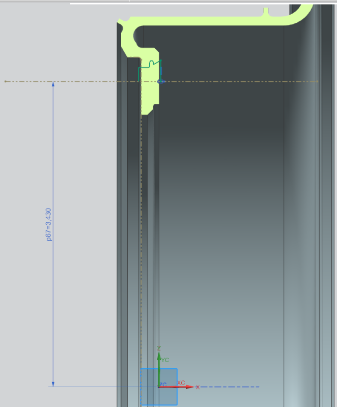
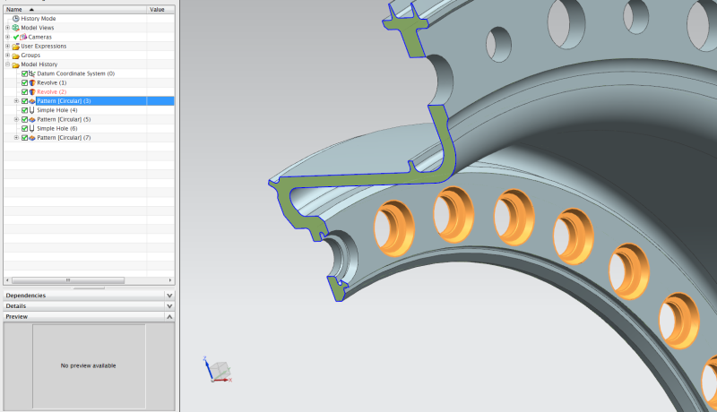
I'd just add an associative Datum CSYS for the center axis of the through hole. I don't worry about having everything linked/parametric to each other with dimensional constraints. I can move a Datum CSYS defining the through hole sketch just as easily as having a dimensional constraint for the PCD (the 3.43 dimension). Both work pretty much the same - see the attached. If you move DatumCSYS(0), DatumCSYS(1) will follow. Through hole location is controlled by the Offset CSYS values in DatumCSYS(1).

Either way, you get the same end result.

DatumCSYS_Axis_Example_NX9.prt


Tim Flater
NX Designer
NX 9.0.3.4 Win7 Pro x64 SP1
Intel Xeon 2.53 GHz 6GB RAM
NVIDIA Quadro 4000 2GB
 
Without having read the whole thread - what I miss most from other CAD systems (Solid Edge, SolidWorks, and Inventor):

1) The idea of flexible sub-assemblies
2) The always live sketch coloring of what lines are fully constrained or not
3) The simplicity and effectiveness of Solid Edge's constraints and user interfaces (this is the best all around CAD program I've used)
4) The simplicity and effectiveness of Inventors Drawing generation application (but the constraint solver was junk)
a) The manual ballooning in NX really needs to be tied to the auto parts list​
5) The BOM structuring capabilities of Inventor
a) Being able to set levels as "phantom" or "purchased assembly" really cleaned up BOMs and item management​
6) The quick view orientation keyboard controls of Solid Edge

A lot of the other things I think are lacking seem like they're being addressed in NX 11.0, so I'm excited to give that a try.
 
Sorry to say this but a better 2D dimensioning in drafting and/or 3D PMI. The new format is very slow with to many clicks.. Since we are comparing to other system AutoCAD, I-deas both have a better 2D dimensioning workflow than NX pre NX9 or post NX9.

Able to Make 3D PDF.

Balloons Tied back to parts list have 2X or quantity in front of the balloon.

Sweep Solid Body.

Span Configurations. Able to control suppression, location of a parts position in assembly arrangements. I-Deas had this. Not all or none.

Revolve with translation. Be able to make a section revolve and translate it along an axis. No Helix or sweep needed. Another I-Deas favorite.
 
Sweep Solid Body.

Coming in NX 11.0.

Span Configurations. Able to control suppression, location of a parts position in assembly arrangements. I-Deas had this. Not all or none.

Not sure what Ideas could do that Arrangements can't since Arrangements were developed to replace Configurations in Ideas. Please provide an example of what you mean.

Revolve with translation. Be able to make a section revolve and translate it along an axis. No Helix or sweep needed. Another I-Deas favorite.

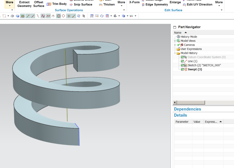
NX has been able to do that for years, however, it might help to think of it as "Translation with Revolve" since you can do this with a Swept feature using an 'Orientation Method' controlled by an 'Angular Law', as shown in the image below (note that it consists of only a 'Line' to define an Axis, a 'Sketch' to define the profile and the 'Swept' feature. NO HELIX NEEDED.):

Swept_Helix_rih20v.png


John R. Baker, P.E.
Product 'Evangelist'
Product Engineering Software
Siemens PLM Software Inc.
Digital Factory
Cypress, CA
Siemens PLM:
UG/NX Museum:

To an Engineer, the glass is twice as big as it needs to be.
 
Not sure what Ideas could do that Arrangements can't since Arrangements were developed to replace Configurations in Ideas. Please provide an example of what you mean.

Imagine you have 3 or more different arrangements. If You added another component to your assembly, you should be able to move this component to the exact same position in only two of the three arrangements with one or two clicks. In I-Deas you could move the component in arrangements 1 and 2 to the exact same position and not arrangement 3. In NX I do not think this is possible. I know you can move the component in each arrangement by its self or same position in all of the arrangement. There were some Great suppress and un-suppress features in this utility also. I think NX has these pretty much covered. Span Configurations the command was called in I-deas.

Sweep Solid Body.
Coming in NX 11.0.
I have heard this before HA J/K We are looking forward to this.

NX has been able to do that for years, however, it might help to think of it as "Translation with Revolve" since you can do this with a Swept feature using an 'Orientation Method' controlled by an 'Angular Law', as shown in the image below (note that it consists of only a 'Line' to define an Axis, a 'Sketch' to define the profile and the 'Swept' feature. NO HELIX NEEDED.):

This is still a sweep. In I-Deas it was all in the revolve tool. I-Deas also had Change in Radius with the translation inside the revolve. I forgot to add this. You could probably still do this as you describe. But it was user friendly for designers, not having them trying to figure out angular laws. This killed us when we converted Our I-Deas data to NX with the CMM (Content Migration Manager) There must be something not the same between the I-deas revolve and your method. After the CMM process all of these features became bodies.
 
sathercs said:
1) The idea of flexible sub-assemblies
Do you mean different positions in different occurences of the same subassembly? NX does that.

sathercs said:
4) The simplicity and effectiveness of Inventors Drawing generation application (but the constraint solver was junk)
Done loads of drawings both in NX and Inventor. Although it's true that Inventor had an edge over NX in the past, nowaydays NX drafting module is practically as robust as Inventor's.

sathercs said:
a) The manual ballooning in NX really needs to be tied to the auto parts list
Manual balloning in NX is tied to the auto parts list.

sathercs said:
6) The quick view orientation keyboard controls of Solid Edge
Not an expert in SE, but in NX the F8 button does the marvellous job of orienting the view.

 
Hi
6) The quick view orientation keyboard controls of Solid Edge
Not an expert in SE, but in NX the F8 button does the marvellous job of orienting the view.

You can also set up your own custom keyboard shortcuts. The default for Orient to the TOP is Crtl+Alt+T you can change it by:

F4, Click on keyboard, Go to View, Orient View Drop-Down, Type in your shortcut, close
 
"A decent high performance roughing strategy - why should I have to pay a significant amount for a plug in like Volumill or the soon to be released iMachining for NX? Take a look outside the NX bubble and you'll see that this is included in nearly all your competitors.

A better tool library, again take a look at what others are doing - especially the ability to use a solid model."

x100
 
Perhaps very pedantic, but I'd love to have a measuring tool that displayed results like everyone else (SolidWorks, Solid Edge, Creo) by showing the X Y and Z components of the measurement vector without having to drag up the "Info" window which is quite cluttered, old fashioned and generally in the way. Also, even in this info window the relevant information could be promoted and highlighted while the "delta" information (which I almost never use) could be pushed to the bottom of the pane which generally requires scrolling to reach. I know I could use the "projection" version of the tool, but that adds a click and prevents getting 2-3 bits of info in a single measurement operation, like XYZ dimensions of a block.

I also really miss the Strength Wizard and the Draft Analysis tools which were included in the basic Mach 1 license in NX 6 and earlier but somewhere along the line got "promoted" to some exorbitant package category requiring a near doubling in license fees. For our small startup, it was cheaper to buy an entire seat of Solid Edge to get these tools than it was to add them to our NX seats.

Please forgive any improprieties if this is not the correct place for these latter requests.
 
What about an easy way to flip the orientation of an isometric or trimetric view around its primary axis when setting up a view in drafting ?

Currently using NX9, planning upgrade to 10

 
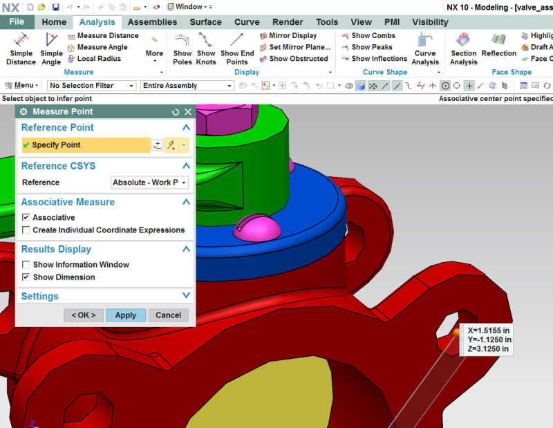
MichaelPrichard when you say the "the X Y and Z components of the measurement vector" don't you mean the I,J,K vector parameters? While we do have the ability to display the X,Y,Z coordinates of a Point using the 'Measure Point' function from the Analysis Ribbon tab...

Measure_Point_y7nsfa.png


...it is true that there is no way, except using Info to find the vector parameters. I've asked that a 'Measure Vector' function be developed so if you would like something like that please call GTAC and them to open an ER (every little bit helps).

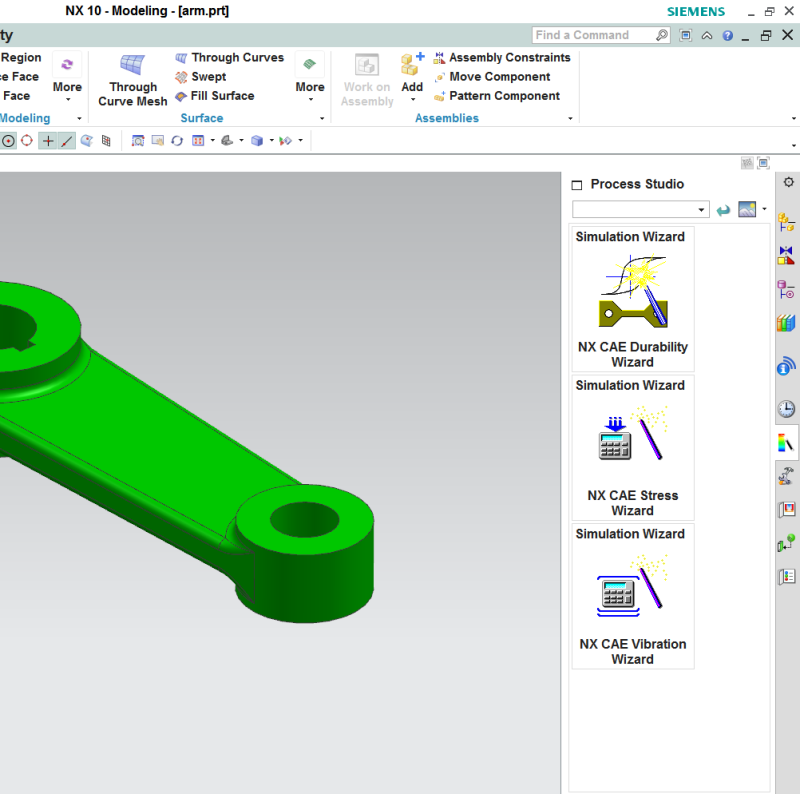
As for your comment about the 'Strength Wizard' that has been replaced with something called the 'NX CAE Stress Wizard' found on the 'Process Studio' Resource Bar tab which is available with all Design bundles:

Process_Studio_ij4thm.png


John R. Baker, P.E.
Product 'Evangelist'
Product Engineering Software
Siemens PLM Software Inc.
Digital Factory
Cypress, CA
Siemens PLM:
UG/NX Museum:

To an Engineer, the glass is twice as big as it needs to be.
 
Lunar7 have you ever tried using the the dynamic X,Y,Z triad in the lower left corner of the display to limit the rotation axis of the display to one of those vectors using the Mouse while holding down the middle button? If you have, great, but note that this also works while editing the orientation of a Drawing view as shown in the video file attached below. Note that you can also select one of the direction arrows displayed in the middle of the display window to get the view normal to one of the primary X.Y,Z directions and from there it only takes a couple of moves using the X,Y,Z triad as mentioned above and you have a new custom oriented Isometric View.

John R. Baker, P.E.
Product 'Evangelist'
Product Engineering Software
Siemens PLM Software Inc.
Digital Factory
Cypress, CA
Siemens PLM:
UG/NX Museum:

To an Engineer, the glass is twice as big as it needs to be.
 
 http://files.engineering.com/getfile.aspx?folder=b661047e-d4f5-4481-9858-8a28baf87e63&file=Edit_Drawing_View_Orientation.mp4
Status
Not open for further replies.

Part and Inventory Search

Sponsor