Eng-Tips is the largest engineering community on the Internet

Intelligent Work Forums for Engineering Professionals

Feedforward: why does feedBACK reduce itself?

Status
Not open for further replies.

jblc

Mechanical
Apr 2, 2009
24
0
0
US
This questions related to feedforward (FF) and feedback (FB) interactions.
Say there's a system who's goal is to keep a car centered in a lane. Say it includes a FF sensor (like detecting sideways wind hitting the car, or an inclinometer to detect the sideways slope of the road), and a FB sensor (like finding the lane markings)

1) Running FF by itself works fine.
Running a FB loop by itself works fine.
When combining them, i would have thought the performance due to combined efforts would be BETTER than either one by itself.

But, what i'm seeing is the exact same performance when FF is run along with FB, as when only FB is run by itself:
- when FF is activated, the FB loop command signal is reduced by the same amount that the FF has contributed. Ie, FB sees a smaller error, and so the performance ends up the same.
- And vice versa: when FF is deactivated, FB quickly fills the gap left by FF.

2) Seemingly, there should be a specific relation needed between the dynamics of FF and the FB loop, ie FF is effective when FB is physically not capable of responding fast enough due to it sensor or loop dynamics, etc., and so FF is needed to fill that gap.
But even in the case with similar dynamics, say a case with suboptimal FB loop tuning, i would have thought that adding FF would strictly improve performance.

Question: In the case that the FF and FB have similar dynamics, how can I set up FB in a way that it DOES NOT take into account the FF's positive impact, so that the combined behavior is higher performance? Ie, so that FB acts with the same commands to the plant, as if FF were inactive.
Naively, one method seems like it'd involve backing out the impact of the FF (ie how the plant would respond to the FF command), and adding that back to the FB loop's error. This seems highly error-proned though, and i'm sure there are many official methods for this...
 
Replies continue below

Recommended for you

How does feed forward "work fine by itself"? Feed forward does not close the control loop (thus open loop). I assume you mean the driver is still providing the feedback. In that case, yes it could work fine for your needs. But feedback is still required.
Feed forward is added to compensate for the problems caused by a time delay between a perturbation and error response, if any. It is not commonly needed.
 
"How does feed forward "work fine by itself"? Feed forward does not close the control loop (thus open loop)."
Feedforward is still a control strategy, it's just not closing a loop -- it's open-loop as you said.
When i say it works fine, i mean that it is effective (just not as effective as FB in the long-term)

"Feed forward is added to compensate for the problems caused by a time delay between a perturbation and error response, if any. It is not commonly needed."
Yep, agreed (hence the statement about FF and FB dynamics). I'm using a car just as an example, but say there's a very high performance application where the delays do matter, and the feedforward sensor can provide input with lower latency that the feedback sensor.

My question is, how can i set up the system to not reduce FB effort even with FF is active?
 
If the feedback loop is countering the effects of the Feed forward control, the loop is not tuned correctly. Perhaps too much gain or too much derivative.
 
Thanks. Agreed that any deriv term could be countering contributions.
In this case, FB is tuned correctly though, since it's a model-based controller that tries to keep the system behavior at the input specs (a higher-level spec like response time constant), and I can verify that the response to test cases is as expected.
So, it's expected that FB will reduce its own corrections when in the regime of properly operating, if FF already does some of that, since the loop is trying to keep the same output regulation characteristics.

But in cases where FB can't maintain that input spec, then I would have thought it simply allows the FF to contribute. Instead, it throttles its input even then.
But you make a good point. Overall though, the additional FF input seems to be viewed as a disturbance, vs as a parallel effort.
Somehow, FF contributions need to be tied to the FB controller, so that FB recognizes that and doesn't react to its contribution.
 
The feed forward should be reducing the error signal to zero in a perfect world, by reacting to measured changes to process inputs. If, as you say your process works fine with with only feedback control, then the feed forward function is completely unecessary and, apparently the cause of your problems. Whatever they are.
 
FF alone is not a perfect correction (hence having both FF and FB), and FB alone works better than FF (as expected).
My expectation, though, is that FF can fill the gaps left by FB, but that doesn't seem to be the case, since FB throttles back when FF is active.
 
Similar challenge integrating FF into a rolling mill control scheme for strip thickness reductions where had been only FB control.

Been several years ago but remember challenges ensuring the response rate of the FB system didn't get excited by the rate of the FF system when enabled, also IIRC, had to dial the FB system back a bit and focus that the gain of the FF system didn't overcorrect anywhere across the spectrum of periodic incoming disturbances from roll and previous-pass coil winding eccentricities. Then there's the phasing / timing challenges between what the instruments 'see' and when the corrections become important.

Came up with a dynamic gain factor for percentage deviations on the entry (incoming, FF) and exit (outgoing, FB) corrections applied to the roll gap.

Essentially suggesting the controller setups, especially for FB, may need to be different based on whether FF is engaged.
 
jblc said:
FF alone is not a perfect correction (hence having both FF and FB), and FB alone works better than FF (as expected). My expectation, though, is that FF can fill the gaps left by FB, but that doesn't seem to be the case, since FB throttles back when FF is active.

I agree that since feedforward is open-loop, it cannot provide perfect correction, but saying feedback alone works better is not typically correct. Your expectation that feedback does most of the work is in fact backwards in most systems with both feedforward and feedback controllers. As to which controller will have bigger output, it depends on the measured vs. unmeasured disturbance sizes and the controller gains for each controller, but generally the feedforward controller is used with large disturbances occurring fairly regularly that can be measured in regulating applications or for set point changes for tracking systems. If you have small disturbances or they occur rarely, feedforward may not be needed, but may be used if desired.

When I taught control theory, I taught that the structure with both feedforward and feedback was usually used as "feedforward control with feedback trim." The feedforward controller is supposed to act fast on large measured disturbances and do most of the compensation for them almost immediately since its output goes straight to into the plant without having to go around the loop and the feedforward controller typically has a simple structure such as a gain or a lead algorithm with high-frequency gain. Meanwhile the feedback controller with its slower negative feedback loop and higher low-frequency gain provides trimming adjustments to compensate for unmeasured disturbances, noise, and plant model uncertainty, as well as stabilizing unstable systems and providing local linearization, things the feedforward controller cannot do. Which will provide the biggest contribution to the output signal into the plant depends on which of those functions ends up being needed most and how the controllers are set up.

xnuke
"Live and act within the limit of your knowledge and keep expanding it to the limit of your life." Ayn Rand, Atlas Shrugged.
Please see FAQ731-376 for tips on how to make the best use of Eng-Tips.
 
Thanks xnuke :), and I agree with that all as well -- typically I think of it as "FB is only needed because FF isn't perfect".
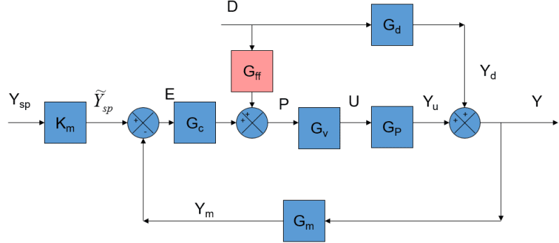
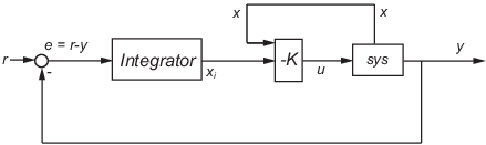
But, that's not what I'm seeing in this instance:
Concrete example, with sims to support:
- FF sensor acts instantly to disturbance, and the plant is commanded to compensate. If only FF is enabled (FB is Off), FF (mostly) rejects the disturbance well-damped and quickly with 500 us settling.
- FB sensor has more delay and thus a slower damped response (due to phase lag from delay). If only FB is enabled (FF is Off), it can rejects the disturbance with 1.5 ms settling, but also trim out perfectly (to use your words)

Given these, i'd have expected that both signals can be summed without issue, so FF acts most quickly, and FB zeros out residual error.
But instead, I see: FF+FB has the EXACT same disturbance rejection settling performance as FB only. Zero change. In fact, as soon as FB sees the correction from FF, the FB command signal ramps up quickly to counteract FF's positive effects. So the result of FF+FB is the EXACT same response as FB-only...except that there's more control effort from FB, due to FB also needing to counter FF.

Conceptually, this makes sense that FB reacts to FF's induced "error" on the feedback sensor. As far as the FB loop is concerned, any changes to the plant that are faster than what's trying to drive through it's designed FB dynamics, are undesirable.
Ie, if FB starts to see an error signal different than what it would expect based on FB's own command (eg due to FF driving faster), FB will change its command signal to counteract that delta and stay on track.

But despite it making sense, how do I resolve the issue and connect them properly?
Somehow FB needs to be made aware that FF is active, so that it doesn't try to cancel out FF's positive effects.

I've thought about injecting the (uFF*plant) to the reference input (so that FB sees the FF contribution as a desired state to drive to), but that introduces a few other complications.

There must be many official ways to do this correctly...
 
Where is PNachtwey when he could help so much on this?

"the FB command signal ramps up quickly to counteract FF's positive effects."

Why would it do this? The point of FF is that by the time the FB portion of the loop has been reached the FF contribution has eliminated the majority of what would have been required by the feedback loop. If FF is working correctly there should be no divergence between the setpoint and the output for FB to do anything with.
 
1) "If FF is working correctly there should be no divergence between the setpoint and the output for FB to do anything with."

Thanks 3DDave, and agreed. This is disturbance FF though, ie no setpoint change. FF is the cmd input to the plant. In this case (as in the image) the disturbance Gd acts on the output of the plant Gp. The disturbance causes an unwanted change in Y (with its evolution given by the disturbance dynamics), which the plant will have to compensate for to keep Y at the same constant desired setpoint value. This disturbance doesn't enter through the plant's cmd source.
So, the setpoint remains unchanged for all time.
feedforward_exercise_azbtrd.png

(This isn't my image, but does show the connection of Gd and Gff to the plant)

2 "Why would it do this? The point of FF is that by the time the FB portion of the loop has been reached the FF contribution has eliminated the majority of what would have been required by the feedback loop."

Yeah, it's confusing that this occurs... FF dynamics are much faster (per previous post), yet FB still cancels out FF (Gff) commands as soon as their effects appear as a tracking error that wasn't commanded by the FB controller (Gc). Changes from FF show up as a tracking error, since the FB loop sees any changes in E (via Y) that weren't changing from a corresponding FB command: FF compensation effectively becomes an unwanted disturbance as far as FB is concerned, a disturbance that happens to evolve faster than the control profile that FB wants to maintain for disturbance-compensation; so FB controller tries to cancel FF out.
This is why FF+FB has the exact same performance as FB only, though FF could significantly contribute to dist rejection.

The above assumes that FB can tell when specific changes in error dynamics are consistent its own commands, or from another source. Ie FB says: "I want all my corrections to be with risetime N, and if they aren't, I'll adjust commands to keep these corrections evolving with risetime N".

In my case, FB is an LQI controller that has gains specified based on the plant model and my input parameters (eg "reject disturbances, with a response with risetime N").
So that's exactly what FB is doing...

Since LQI is basically PID but with special gains and using both pos and vel feedback (here, the vel is from a state estimator), it seems that at the least, the D term acts harder when the vel change (from FF) is faster that it would expect from its FB-only commands.
Hence, FF+FB has the exact same performance as FB only, as long as FB has enough control effort to counteract FF.

3) This leads to another point is confusing to me: if FB can cancel out FF's effects, then isn't FB fast enough to do FF's job? I don't have an answer to that, since when FB runs by itself (no FF), it can only reach a certain disturbance rejection settling time performance due to FB loop rate and sensor delay. Ie FB is slower by about 3x per my last post, to avoid significant settling oscillations. FB response (reachable plant velocity) can be faster, but the plant will oscillate.
--> I'd would appreciate any insights from anyone on this: if FB canceling FF is possible, does that mean FB should be able to also achieve FF's response? Or is there a difference between constantly canceling the start of some faster dynamic (ie from FF), vs stably commanding that same faster dynamic in full (via FB)?

Overall, I don't know how to set up the FB loop to where the error going to 0 is okay if it's due to FF's commands, even if it's then faster than the FB disturbance rejection parameter spec that i've specified, since as far as i know LQI with a state estimator, is basically equivalent PID with an extra velocity sensor.

P.S. If the FB loop rate were SO low that FF could 100% complete all plant corrections before FB even sees a new measurement update Y, then FB would just see a Y = 0 (ie no error) and not try to reverse FF's effects. But in the case I'm working with, the FB loop and sensor update rate is fast enough that changes from FF are seen as they occur...ie FB will ALSO try to correct the disturbance, just more slowly.
 
Ah -- a clue finally occurred to me.
There is actually a difference between PID and LQI. They both have equivalent-type correction terms (proportional, integral, derivative), but LQI does NOT use error as inputs to P and D: LQI uses state feedback (which could be from sensors, or estimators). It does use error for I though.

Eg here:
[URL unfurl="true"]https://www.mathworks.com/help/control/ref/ss.lqi.html[/url]

lqi1_xwagv3.png


I'm not totally sure yet of the implications, but one thought is that with PID the error gets smaller when FF acts, and that's desirable, so PID doesn't try to cancel FF.
In contrast, LQI looks at the state directly, and if the state deviates from where LQI thinks it should be (eg when FF tries to help the system), LQI will try to cancel FF: since the error isn't a factor here, LQI wouldn't know that a changing state is better or worse...it just knows that it's changing from its desired trajectory.

So, it seems there needs to be a method to tell LQI to not cancel out FF.
Does anyone know of any techniques, or have suggestions?
 
Where is PNachtwey when he could help so much on this?
I am here now.
I am going to use motion control as an example.
The output due to feed forwards are generated by mulitpying the target speed by the velocity feed foward and adding the target acceleration by the acceleration feed forward gain. Our motion controllers also add the target jerk x the jerk feed forward gain.

I derive the feed forward gains from the inverse of the open loop model. I get the open loop model from system identification.

The closed loop gains should not affect the feed forwards nor should the feed forwards affect the closed loop gains but it but feed forwards will reduce the control output from the closed loop gains.

In short, the more accurate the open loop model, the more accurate the feed forward gains can be calculated. This resuslts in the control out being very closed to the required output even without feedback. If the model is accurate to within 2% then the closed loop control only needs to correct for that 2% which means the error is reduced by a factor of 50.


I have many videos on my YouTube channel "Peter Ponders PID"

Look the controller gains. The feed forward gains do not change as a move the closed loop poles to the left on the s-plane but the closed loop gains increase significantly. The are formulas for ALL the gains.
BTW, I was testing the picture in picture feature of my screen recorder, not the code.


Peter Nachtwey
Delta Motion
IFPS Hall of Fame Member
 
Thanks for the reply PNachtwey.
What you mentioned is already clear, but I think my issue is more related to the full state feedback (per my last post), which acts differently than PID.

"The closed loop gains should not affect the feed forwards nor should the feed forwards affect the closed loop gains but it but feed forwards will reduce the control output from the closed loop gains."
Totally agreed, and this is why the issue is so confusing, since this clearly isn't occurring. Usually each path can be tuned independently (FF, and FB using models), and then both are activated and do not interfere, and yield higher performance -- but not in the case of LQI.

I mentioned in my last post that with LQI i think i need a way for LQI to understand that FF is a desirable change in system dynamics, vs being viewed as a disturbance that needs to be canceled, since LQI is trying to control with designer-set system dynamics specs. This is different than PID, which acts on the error signal and does not have a parameterized target behavior per-se, and so is an independent loop from FF.

Anyway, see my last two posts for more details, and some specific questions.

Any help is very much appreciated :D
 
Now I see what you are getting at.
The closed loop gains can interfere with the feed forwards if the closed loop gain is only used in the feed back path ( act only on changes in the actual position instead of the error ).
Simply put, there are different forms of PID.
The 22 Dec picture shows a I-P controller. There are PID, PI-D,I-PD and different variations where the P and D gains are different in the forward path from the feed back path.
The difference between PID and the PI-D is that the D term is in the feed back path only. The D term only acts on the actual position, not the error between the target and actual position.
The I-PD controller has only the I term in the forward path. This means that only the I term is multiplied by the error. The P and D terms are in the feedback path so the P and D terms only act on the actual position or changes in the actual position.

Feed forwards will only work well if all the closed loop gains are in the forward path like a normal PID or PI. Therefore the I-P controller will not work with normal feed forwards. However, there are other ways of implementing the feed forwards. Another way is to exaggerate the motion of the target position to compensate for the lagging I-P controller.

Gains in the forward path create closed loop zeros. Closed loop zeros can extend bandwidth. Closed loop zeros are also sensitive to noise, coarse feedback etc. Closed loop zeros can also cause resonance peaks or unintentional notch filters. Most people don't worry about the closed loop zeros unless it messes up the response and then they don't know what to do about it. It is possible to place the closed loop zeros as well as the closed loop poles.

A mathcad pdf showing the different forms of PID by showing the response, bode plot and pole zero plot for each.


Peter Nachtwey
Delta Motion
IFPS Hall of Fame Member
 
Thanks PNachtwey :)

The closed loop gains can interfere with the feed forwards if the closed loop gain is only used in the feed back path ( act only on changes in the actual position instead of the error ).

The difference between PID and the PI-D is that the D term is in the feed back path only
To make sure i interpret correctly what you mean by "is only used in the feed back path" and feed back path only: do you mean that that feedback path only is the inner path that doesn't go through the error path? (the error is r-y in my Dec 23 post) I ask because the I-PD has all three going through a feedback path, except (as you said) I is the only one tied to the error.

If that's what you mean, then yes, my update on Dec 23 21:03 shows that LQI is I-PD: only the I path is in the setpoint error path, and P and D are driven directly using feedback of two states x (the two states are pos and vel).

Feed forwards will only work well if all the closed loop gains are in the forward path like a normal PID or PI.
Just to learn more, why is that?

"Another way is to exaggerate the motion of the target position to compensate for the lagging I-P controller."
Do you have any proposed methods for doing this? I tried:
a) connecting FF to the setpoint as well (with a >1 gain), in addition to the u cmd going to the plant. For this, I had to feed the FF command through a plant model, so that the position change appeared at the setpoint; if i didn't do that, the input to the setpoint would be the inverse-dynamics FF command signal, which is nonsensical.
This approach did not achieve what i was hoping, since the response dynamics was still limited by the FB loop, due to the integral still acting on the setpoint error.

b) So then, to the above strategy, I also tried adding setpoint FF, so that this setpoint would bypass the integrator. This might work, but I didn't know what the setpont-FF function should be, since the input to the setpoint is a position. If i then add an inverse dynamics block, then I'm right back to where I started before connecting this setpoint-FF path: the FF cmd fed directly into the plant. So nothing is gained.
A second issue is that, since i need to pass the FF command through a plant model, this will (over time) drift away from the actual plant state.

"Most people don't worry about the closed loop zeros unless it messes up the response and then they don't know what to do about it. It is possible to place the closed loop zeros as well as the closed loop poles."
What do you advise people do to place the closed loop zeros, when it's messing up the response as in this case? I could change the I path, but the I is currently where it is, due to the needed/stable FB dynamics.

"A mathcad pdf showing the different forms of PID by showing the response, bode plot and pole zero plot for each..."
Thank you! This is a great comparison. It's not clear to me why the I-PD controller has such poor tracking results, since for LQI (I-PD), the tracking error in my sims is very small.
 
Feedback is negative!
A simple incremental PID is
u(n)=u(n-1)=Ki*(tar_pos-act_pos)+Kp*(tar_vel-act_vel)+Kd*(tar_acc-act_act)
An I-PD is the same but the tar_vel and tar_acc are set to 0 because the Kp and Kd act only on the feed back state, not the target.
u(n)=u(n-1)=Ki*(tar_pos-act_pos)+Kp*(0-act_vel)+Kd*(0-act_act)
It should be obvious that the output will be lower because we are not adding Kp*tar)vel or Kd*tar_acc

Another way to implement feed forwards is to exaggerate the target trajectory so when the I-PD lags the actual position, velocity and acceleration are equal to the unexaggerated position, velocity and acceleration.
Go to page 8/8 and look at the plot. There us a line called CFF that is the exaggerated target trajectory. This is what the I-PD tries to follow but because of the lag due to the I-PD it ends up being the same as the desired target trajectory. I called this command feedforward at the time because I had no other name for it.

There is nothing you can do about zeros using simple PIDs. There are ways to place the closed loop zeros. I showed how in the PID comparison pdf. I learned by looking tha the BOde plots are affected by the closed loop zeros as I moved the closed loop poles. I like making Bode plots and pole zero charts to see the inter action. Sometimes I would place the closed loop poles at and ideal location only to have the closed loop zeros create a resonance peak or a notch. I learned how to place the closed loop zeros too.
Then the PID because this
u(n)=u(n-1)=Ki*(tar_pos-act_pos)+Kpz*tar_vel-Kp*act_vel+Kdz*tar_acc-Kd*act_act where Kpz and Kdz are the forward path gains and Kp and Kd are the feedback path gains. Now there are two more gains to compute.

Much of this is not in a book. I am self-taught but I have been at this for a long time. I have about 800 Mathcad worksheets with many combinations of control worked out. I could easily fill many books.

Hopefully you understand some of my abbreviations.


Peter Nachtwey
Delta Motion
IFPS Hall of Fame Member
 
"Feedback is negative!"
Yeah definitely :D Not sure what this is referencing, but that's certainly clear.

It should be obvious that the output will be lower because we are not adding Kp*tar)vel or Kd*tar_acc"
Are you responding to my question on why your I-PD is more poor tracking?
LQI has excellent tracking capabilities, even though they are not acting on the error. My sims do not show poor tracking.

"Another way to implement feed forwards is to exaggerate the target trajectory so when the I-PD lags the actual position, velocity and acceleration are equal to the unexaggerated position, velocity and acceleration."
Go to page 8/8 and look at the plot. There us a line called CFF that is the exaggerated target trajectory. This is what the I-PD tries to follow but because of the lag due to the I-PD it ends up being the same as the desired target trajectory. I called this command feedforward at the time because I had no other name for it."

Thanks! This is something that I tried (as mentioned earlier) given feeding FF into the setpoint reference, but I used a different approach and perhaps yours works better :) In your plot on page 8, how does "Actual" response compare when Cff is present, or not present? Would it be the same output as in the previous mathcad you shared?
 
I am responding to the poor tracking. Kp*(0-act_vel) subtracts from the control signal all gthe time. Kp*(tar_vel-act_vel) does not. If the actual trajectory is following the target trajectory the change in control output is zero whereas the P and D gains subtract from the control output on an I-PD controller.

Mine works. It should be obvious that if you invert the closed loop transfer function and multiply it by the closed loop transfer function the result is 1 so the actual is equal to the target.

At the bottom of page 7/8 i call IPVA with rff(n) instead of r(n). rff(n) is the exaggerated reference the controller tries to follow but due to the lag the actual trajectory matches target trajectory.

I am not sure if I understand the question.

Peter Nachtwey
Delta Motion
IFPS Hall of Fame Member
 
Status
Not open for further replies.
Back
Top