Continue to Site

Eng-Tips is the largest engineering community on the Internet

Intelligent Work Forums for Engineering Professionals

  • Congratulations KootK on being selected by the Eng-Tips community for having the most helpful posts in the forums last week. Way to Go!

FEM Flat Slab Design 4

Status
Not open for further replies.

Bubik

Structural
Mar 15, 2016
103
Hi everyone

I am really stuck with the design of a 350 mm thick flat slab (no column drops). The structure is a podium supporting five floors above. As the structure has an irregular column layout, line loads and point loads located in random areas I intend to design it with FEM. I previously did some design of a flat slab but with a regular column layout using FEM. I then used the column/middle panel strip method to average peak moments over the columns so I could specify the reinforcement. In this case however I just don’t know how to apply the strip method due to the irregularity of the column layout as I don’t know how to define a panel width. Maybe you guys know some other method?

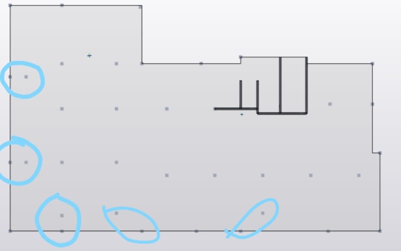
By the way I am using Tekla Structural Designer software and below there is a plan view of the podium.
 
 https://files.engineering.com/getfile.aspx?folder=5f8bb136-e267-4eb3-8832-11d3ce8fbb19&file=Slab.PNG
Replies continue below

Recommended for you

JoshPlumSE said:
Setting the Width of Design Strips
One of the most important design considerations is how wide to set the Design Strip. If the width is set too large, then the program will average out the moments and shears over too wide of a region. This would result in unconservative design moments and shears. Similarly, if the strip is set too small, then the effect of stress risers in the FEM analysis will be over estimated and the design will be over conservative.

The setting of the design strip widths is truly a matter of engineering judgment. RISA Tech, Inc. makes no endorsement on what methods would be most appropriate.

As a new Engineer, I think this was one item on the top of my list for analysis issues that bothered me the most. I would try and get guidance from some of the senior Engineers about this topic and they would all side step the issue and never really give me a definitive answer. Over the years, I sort of rationalized my own method but I still question myself from time-to-time.
 
strctPono -

Yes, I ran into the same problem. Large mat foundation for a huge vessel. Wasn't sure how to design the reinforcing for it. Not much help from others.

In the end, I was conservative and uses the punching shear width around the pedestal. Granted, I think minimum tension steel may have been sufficient because punching shear is what dictated the thickness of the mat.

But, this is one of the reasons why I devoted so much effort to documenting this for RISAFoundation.... because it was a design conundrum from when I did real engineering. Granted, I never took any definitive stance on how to do it. My tendency was always to be a little more conservative than the ACI strip method or the zero shear method. So, while those were probably the most rational methods I encountered, I didn't want to fully endorse them.

 
Have a look at the 'Lines of Zero Shear' method for working out strip widths.

Transfer slabs with irregular grids are one of those things that you will look at it from every which way to satisfy yourself it's strong and robust enough. This would include a nice concoction of FEM analysis, 2D strip analysis and hand calcs.

 
JoshPlumSE

PTI publication Design Fundamentals of Post-Tensioned Concrete Floors is great, do you happen to have any more publications like that on the subject?
 
Do you need to use the Overstrength combinations due to the vertical irregularity?
 
JLNJ

It is the first time I hear about the overstrength combinations..would you please elaborate on thaT?
 
It seem like you might have a vertical discontinuity as in ASCE 12.3.3.3.
 
Trenno

Spot on, that is exactly what it feels like
 
Hi,

350mm is very thin for a transfer slab. Don't forget to account for Mxy moment & Shear due to unbalanced moment, especially around the circled area
InkedInkedSlab_LI_njtkn0.jpg
 
This is what I've observed from the past experience that, the more the rigid a slab is, the more uniform stress/force distribution you will get.
So for a thin mat such as yours, which is also supporting load from 5 upper floors, I'll really like to be on the safer side than the economical.

Most have already specified that, taking a certain width to average out stresses is really an engineering judgement.
This is what I have done in the past where there is a vast change in magnitudes from meshed to meshed area, I select, those meshed areas elements around the column with relatively less gradient in the magnitudes, called out the stresses/forces of the selected areas and then design for an average of stresses for those meshed areas only.
 
Bubik,

A good place to start is to define your major load paths (orthogonal) in the 2 directions (without a computer!) for the applied loads and associated support layout.

This will show you where your support strips (column strips in a simple flat slab) and span strips (middle strips in a simple flat slab) are.

Overlaying that on your fem result will then allow you to logically associate different widths of the slab Bending moment diagrams to each strip.
 
Don't forget to account for embedded conduit/pipes and other penetrations. Those could become critical if your design is already borderline.
 
Thank you all for your input..it is great
 
Status
Not open for further replies.

Part and Inventory Search

Sponsor