Continue to Site

Eng-Tips is the largest engineering community on the Internet

Intelligent Work Forums for Engineering Professionals

  • Congratulations waross on being selected by the Eng-Tips community for having the most helpful posts in the forums last week. Way to Go!

FET switching question 4

Status
Not open for further replies.

knowlittle

Materials
Jul 26, 2007
192
I have a USB-based data acquisition card. I am using its digital output to turn on a solenoid. But there is a mismatch in power. Digital out can sink/source 15 mA. Solenoid needs 24 VDC 8W. I would like to build a MOSFET switch.
1. I will use a logic level N-type enhancement FET (RFP30N06LE). 60V 30A ESD rated, Rds 47 mOhm, Vgs (th) 1V min 2V max.
2. I will put the solenoid between +24V DC and Drain.
3. Connects all grounds together (FET Source, 24 VDC power supply ground, USB data acquisition board ground)
4. I forgot to add a flyback diode across the solenoid.
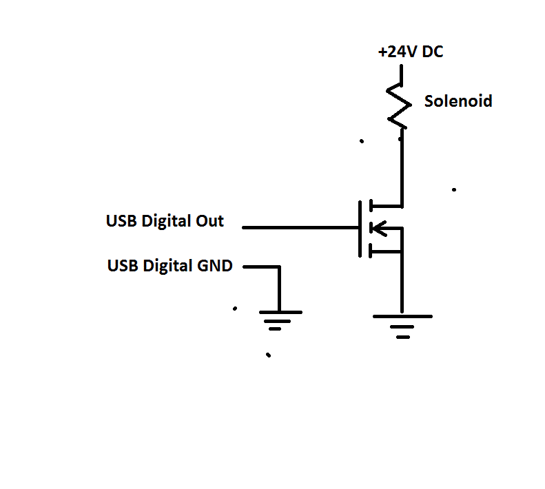
Diaital_Out_to_Solenoid_interface_i3hpx2.gif

Link for the MOSFET datasheet is here
Do you think this will work?
 
Replies continue below

Recommended for you

Do you have "ON/OFF" capability in the USB Contact? USB doesn't work like that, normally. And I doubt if your coard can be configured so. But if it can - yrs it could work. But I'd rater use a simple BJT.

Gunnar Englund
--------------------------------------
Half full - Half empty? I don't mind. It's what in it that counts.
 
I agree with Skogs; a BJT transistor will be much easier to implement. FETs are easily damaged by static. If you do use the FET, put a resistor (100 ohms or so) in series with the gate, otherwise you'll get lots of oscillations when the FET turns on and off.

You might also consider a relay if this doesn't have to switch very often.

Z
 
I don't think he's trying to control it with the USB lines directly, guys.

With a back-EMF diode thrown in, I see nothing wrong with the circuit. I, too, would throw in a resistor on the gate... something above 333 ohms to keep the initial current rush below 15mA.

Dan - Owner
Footwell%20Animation%20Tiny.gif
 
The basic circuit concept as shown will probably work. I've used the same sort of design several times, such as a very crude audio amplifier (a bit square wave) where a low power tone from a sound chip was blasted into a large horn speaker via a big FET to form a siren.

One still needs to double-check the numbers, such as R-on times current = power. Plenty of details to check, even with a simple circuit.

 
Thank you for the advices. I have to buy the mosfet, but have a drawer full of transistors and found TIP 112 darlington transistors. Ic max 2A, more than my 0.5A need. So here is my first transistor calculation.

Emitter cutoff 2 mA max. Datasheet does not list min saturation current. Assuming 3 mA will push into saturation,
3 mA = (5V - 1.4V)/Rb. Rb=1.2Kohm.

In place of MOSFET, I will use this transistor with base resistor 1.2K. There will be a flyback diode across the solenoid coil, 50V 2A or higher. Will this work?
 
"Datasheet does not list min saturation current"

The curves in the datasheet provide ample information. Emitter cut-off current is <<not>> related to your calculation. The datasheet curves basically say that Ib over about 500 uA is sufficient for your case of 0.333 A Ic

TTFN (ta ta for now)
I can do absolutely anything. I'm an expert! faq731-376 forum1529 Entire Forum list
 
Thank you for the explanation. Now I know what those graphs are for. I didn't know Ib for saturation is so low. I will increase Rb to 2Kohms and go from there. Thank you, all, for guiding me step by step.
 
Also, do not confuse the operation of a BJT and a MOSFET as being readily interchangable. They serve very different purposes. One can force a BJT to act as a MOSFET (and vice versa with the FET), but they're operation in those regions is not ideal by any stretch.

For a solenoid on/off switch, the FET is the proper tool.

Dan - Owner
Footwell%20Animation%20Tiny.gif
 
Darlington is not a good idea because of the 2 x VBE ,
will add to the Mosfet circuit 2 Resistors 1K ohm from Line to Gate and 500K ohms from Gate to Source=Ground ,
any feedback : daveross100@gmail.com
 
If you want the solenoid to drop the load fast then add a zener diode in series with the flyback Diode. Otherwise the current will circulate in the freewheeling path for up too a few hunderd ms and prevent release.
 
Solid state relay isolates the power circuit from the control circuit. Simple, cheap, works first time.

Building the circuit is more educational though. :)
 
Status
Not open for further replies.

Part and Inventory Search

Sponsor