Continue to Site

Eng-Tips is the largest engineering community on the Internet

Intelligent Work Forums for Engineering Professionals

  • Congratulations IDS on being selected by the Eng-Tips community for having the most helpful posts in the forums last week. Way to Go!

Field diodes blowing on 1000 kW diesel generator 2

Status
Not open for further replies.

Djim cameron

Electrical
Oct 18, 2018
6

We been having a problems with the positive diodes blowing (4 times) of the diode block on a 1000 kW diesel Generator. This generator is one three generators at a non-grid connected DGS station. The incidences that I investigated the generator would be online by itself supply a load of 60%. Generator would quit producing voltage, AVR (decs250) would alarm over excitation, generator would trip on under voltage. any suggestions on what would be causing this? What generator stator, rotor, excitation system tests should be done? THanks
 
Replies continue below

Recommended for you

What kind of excitation system is this?
Rotating exciter or via slip-rings?
Any diagrams?
It happens after start? Not during synchronization?
Bad cooling may be a reason. Especially if the diodes have been replaced with little regard to heat-paste or heat-pads.

Gunnar Englund
--------------------------------------
Half full - Half empty? I don't mind. It's what in it that counts.
 
It is a rotating exciter system I will have to find or make diagrams.

This excitation system, consisting of Permanent Magnetic Generator PMG that supplies power to Basler AVR DECS250. The AVR supplies DC to exciter field, the exciter armature which rotates creates 3 phase, which is connected to the diode block, which also rotates. The diode block rectifies and supplies the DC to the main rotor.

Diodes do not blow during start or sync. generator was on-line (only generator on-line) producing 60% power at 600 volts 60 hertz.

Probably not cooling. The diode block is connected end of shaft spinning at 1800 rpm. Proper heat transfer compound used.

Thanks
 
ugh. Could be a winding problem and the regulator is over-currenting them in an effort to meet the output requirements. Meggering may be in your future.

Keith Cress
kcress -
 
Such repeat diode failures normally mean main generator rotor interturn shorts. An increase in the exciter field current, which you can measure, on generator no-load will be seen when such turn shorts occur. AC pole drop test and/or a surge comparison test on main rotor winding will confirm any turn shorts.

Muthu
 
You should be able to go into the metering screen on the Bestcomms Plus software and read the field volts and field amps, compare to the other units. Do you have the software? It is a free download from Basler.

If only one polarity diodes are failing, and the surge suppressor has not blown, then I agree likely a rotor problem.

Do you know the rated field volts and amps of the machine? Is this a new machine or a machine that has been in service for some time.

600VAC at 60Hz, is this unit in oil/gas service, like a drill rig?

Can you provide specifics on the unit, manufacturer, model, serial number? May help get you a more specific answer.

MikeL.
 
It may be Canadian, Mike.
600 Volts is a common standard in Canada.
Some rental firms supply auto transformers (often open delta) with 480 Volt generators to provide temporary power to 600 Volt plants.
We also see Gen-sets that may be configured for 208 Volts, 480 Volts or 600 Volts.

Bill
--------------------
"Why not the best?"
Jimmy Carter
 
Bill,

A couple of years ago there were a number of similar failures in 1-1.5 MW units in oil and gas service in North America (US and Canada locations). Some additional specifics from the OP may help determine if this could be another of those issues.

A DECS250 on a 1MW generator seems like overkill too me, so raises the question as to what exactly this unit is doing, may be something else here that isn't readily apparent.

Some details about what kind of load the unit is driving may also help.

MikeL.
 
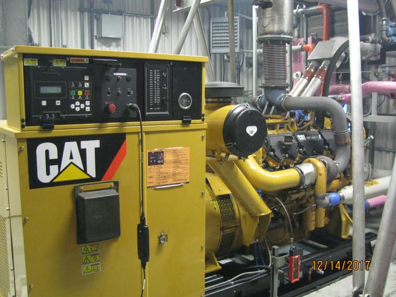
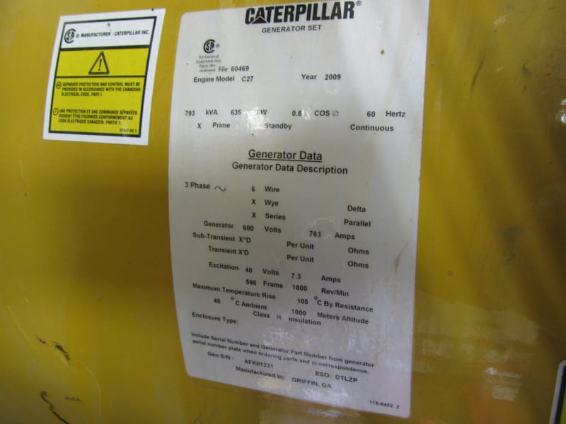
The generator is a CAT C27 635 kW 600 Volt 60 Hz (I found a picture of the nameplate). The station supplies power to a small off grid remote community, air access only summer, ice roads winter (IRT have been there). There are also two 3516 at this site. We run these generators via PLC control to best fit the load. We use Woodard DSLC2 for load control, sync, load share, etc. and the Basler DESC250 (AVR)voltage regulation and var sharing. BestComm software is used to set up the AVR and to view the metering of the AVR. I'm trying to avoid having to remove the rotor until I'm sure that has to be done. What test could be performed with the rotor still in place.

I tried to attach a few pics. Thanks JC

IMG_5700_gynepi.jpg
IMG_0524_myq73g.jpg
 
Have you read the field amps and volts on the DECS software while under load? Have you compared those readings to the other units? Most CAT generators in a similar size range and voltage will have similar field characteristics. The excitation volts and amps on the generator nameplate are for full kVA load. No load rated voltage field volts on these is usually around 12-14 VDC.

So that set has been around for a while, when did the problems start occurring?

First test I would do is a megger or insulation resistance test of the rotor, have you done that? If so what are the readings?

I have done pole drop tests in place on generators that size. I use a variac and apply 80-100VAC ( use a voltage easy to divide by the number of poles, a C27 at 60Hz is usually an 1800 rpm machine, so 4 poles)to the main rotor leads, then measure the voltage drop across each pole. Note that there are two pole jumpers at the rear or non-drive end of the rotor, and two at the front or drive end. You will find on getting a measurement on the front jumpers to be a real pain for that frame size. I have found gross problems just be doing measurements at the rear.

I also take one set of reading, then rotate the engine about 45 degrees and take the readings again. If the readings are different I will rotate the engine again and take one more set of readings.

A pole drop test while the rotor is still inside the stator is not the preferred method according to what I was taught, but it can lead you to finding problems.

Try to do a good visual inspection of the pole jumpers if possible, every once in a while we have found bad connections on the jumpers, show up as discoloration around the connections.

You can also try to a winding resistance check on each pole, but I can tell you that is usually pretty hard to do on gen ends and get reliable results.

Do you notice any increase in vibration on this unit? Usually rotor problems can also show up as increased vibration.

Hope that helps,
MikeL.
 
If you have the original baseline rotor winding impedance (whether provided by OEM or collected during in-house maintenance), then you can measure the rotor impedance now and compare them. A turn short would show a lower impedance. For this test, remove the main rotor leads from the rotating rectifier assembly, supply 110/220 V AC to the rotor leads and measure the current with a clamp-on meter. Voltage/current will give you the rotor impedance.

Muthu
 
- no load field amps 2.4A, field volts (9.5 - 11.5 V)
- 60% load field amps 2.9A, field volts (12.0 - 13.0 V)

- Generator has 22,000 hours probably 7 years old
- 3-4 months ago was when the diodes blew for the first time, they would get replaced and generator placed back in service, would run for a while then diodes blow again, I believe 4 times they have been replaced,
- I have been told that the meggar test were performed and the results were good
- A pseudo pole drop test was performed and the results looked linear throughout range 0 - 150 volts, did not measure across each pole, will probably have to remove rotor to perform this test, will have to investigate if access to pole jumpers is possible without having to remove the rotor
- I did not notice abnormal vibration from this generator, don't believe we have a base line
Thanks MikeL

- I don't believe that the a baseline rotor winding impedance test was performed during commissioning, so nothing to compare to. I will contact CAT to see if they have any results.
Thanks Muthu

I'm aware of a generator where diodes were blowing and they would be just be replaced, ended up destroying generator.

I plan to perform the pole drop test again and hopefully I will be able to measure the impedance of each pole at the jumpers. Need to find what the original results were to compare.

I leaning towards having to remove the rotor, perform thorough testing, then repair or replace rotor. This is a remote site so it's not easy to get there and winter is coming.

Thanks JC

 
I cut some info out of an old training handout for a 4 pole rotor pole drop test, attached in a word doc.
Before you test, LOTO the engine, make sure it will not crank or start.
You may be able to see one or two jumpers from the rear, depends on vintage of the rotor, older rotors had two of the jumpers in the rear and one in front, either way you can get an indication if there is a problem.

If you want to verify validity of the testing, rotate the engine about 45 degrees and repeat the testing, results should be close to the same if the test was properly done. This test won't test each pole individually, but if the results are uneven, you have a problem with the rotor and you know it is one of two poles you tested.

This will diagnose a constant problem, if the problem is intermittent then when stopped the unit may test ok. Because of the info you provided so far this may be an intermittent issue. Several years ago we had a run of rotors with winding problems, run initially for some time, started failing diodes, hard to pin down, most of our diagnosis was done using vibration analysis and a DECS200 so we could do datalogging. Gens would run anywhere from 2-20 hours then trip, paralleled units would trip on loss of field, single units on under-volts. All of the units that suffered damage to the generator were paralleled units, we found in several instances the loss of field settings didn't properly protect.

Have you considered using the datalog feature in the DECS250? It works quite well and may give you a better idea what is going on. Based on the info you have provided it appears the Diode Monitor feature is not enabled, but you should still be able to monitor the ripple current in the DECS datalog to see if a change occurs if the field volts/amps go up.

Hope that helps, MikeL.
 
 https://files.engineering.com/getfile.aspx?folder=7ad85e4b-3659-434d-9147-aeb30497e026&file=Field_Pole_Drop_Test.docx
I'm surprised that the vibration caused by a rotor bend can be detected through the high background vibration inherent on a recip engine. Has anyone actually done this successfully? We could detect it on a smooth-running turbo machine with a sensitive Bently Nevada monitoring system, but it was never at a level approaching 'trip'.

What diode type are fitted to this machine - studs or hockey pucks? Pucks are prone to damage during installation if done by the inexperienced / untrained. A small rotor is more awkward to work on, and the pucks are smaller, so plenty scope for unknowingly damaging the diode during installation.
 
I have actually used vibration analysis to help troubleshoot a number of rotor problems over the years. But you can't use the vibration readings alone. I used to have a "test" DECS200 AVR to use along with other tools, and would try to compare a change in field output and ripple current to vibration levels. Was easier on units with stable loads or paralleled to grid, hardest ones to troubleshoot were on high cyclic loads like drill rigs. The 1st order magnitude usually doesn't change dramatically, but it can be measured in a lot of cases, at least on the units I have worked around. You just have to understand why it is changing.

Some times finding a problem was easy, both CAT and Stamford had issues with pole jumpers and their connections, both right after making rather large production changes, I guess someone tried to save a little money and it came back to bite them both in a pretty large way, once identified pretty easy to correct, but not cheap, pulling a rotor in the field sucks. Kato several years ago had problems on certain frame sizes after making changes to rotor production in their facility, as the rotor poles were being wound a part in the machine was nicking the wire, some affected units actually never failed, but several did, showing up as mostly internal shorts on a pole winding and in a few cases grounded windings.

A CAT generator like the OP has uses a packaged diode system, a heat sink plate with a positive diode pack, a negative diode pack and a surge suppressor. CAT only sells the assembly, if they are just changing a single diode pack they are using aftermarket parts. The packaged diodes were actually pretty rugged, only real issue we had was no one ever seemed to use heat sink compound when mounting them and over the years several failures all seemed to have excessive heating as root cause of the failure. CAT and LS made a decision to not provide individual parts and only sell the complete rectifier assembly, supposedly claims went down and problems reduced significantly. Actually there were some other issues going on at the time with suppliers and cost reductions, and at one point counterfeit parts, but lately diode problems on these types units don't seem to show up much anymore, at least in my experience.

Sometimes in cases like this it isn't actually the main rotor, I had one a couple of years ago that the rotor was both rewound and then replaced with new, but they kept reusing the PMG and Exciter stators because they tested "good", after several months of trying to figure it out, turned out to be a problem with the PMG stator, when a larger load would come in (in this case a larger motor with across the line starting)the PMG output would drop off (but not every time the load was applied), the AVR would go full field, hit the OEL and trip on under voltage, sometimes we would find a diode failed, sometimes a surge suppressor, something nothing was damaged and it would restart and work fine for hours, days or weeks. Changed the PMG stator and no more problems.

The nature of an intermittent problem, get lucky and find it early, or keep putting back into service and see where it fails, have customers who do it both ways and can't honestly which is really better in all cases, depending on the application and other factors that get involved.

Hope that helps, MikeL
 
What I find unusual is that only the positive pole diodes go bad, never the negative pole. Generally the on-rotor exciter system is not grounded. This should probably be something you should check. If it is grounded, then find out from the manufacturer if it should be grounded. Stupid question are the positive pole diodes being replaced with the correct replacements? Second stupid question Has anyone checked the negative pole diodes? If the diodes are insulated from the heat sink, has this insulation on both the negative pole and positive pole been looked at?
 
djs,

Sometimes the rotor earth fault only occurs when the windings shift slightly under the centrifugal forces present at sync speed. They measure clear when stationary. This type of fault is an absolute pig to diagnose on a rotating rectifier machine; by contrast it's fairly straightforward on a slipring machine. On larger machines it is possible to fit an air-gap search coil to monitor the rotor flux, but I've never seen one deployed on such a small set.
 
How about energising one pole of the stator windings with low voltage AC.
Then put long leads on the rotor connections so that you can rotate the rotor several times before running out of slack.
Look for rotor voltage anomalies as the various rotor poles pass the energized stator pole

Bill
--------------------
"Why not the best?"
Jimmy Carter
 
Thanks for all the suggestions.

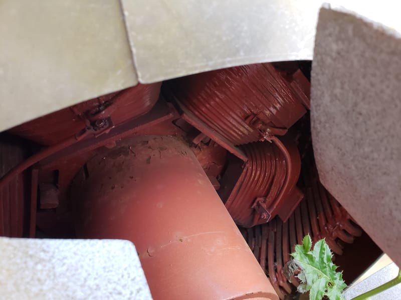
I'm arranging a trip to site to perform some tests, that include the pole drop test with 45 rotation. hopefully I can get on the pole jumpers. I've attached a picture showing the jumpers on a 3512 rotor (6 pole). I'm thinking the C27 has similar jumpers where measurements can be taken. The PMG produces 90 volts at 240 hz @ 120 and 240.

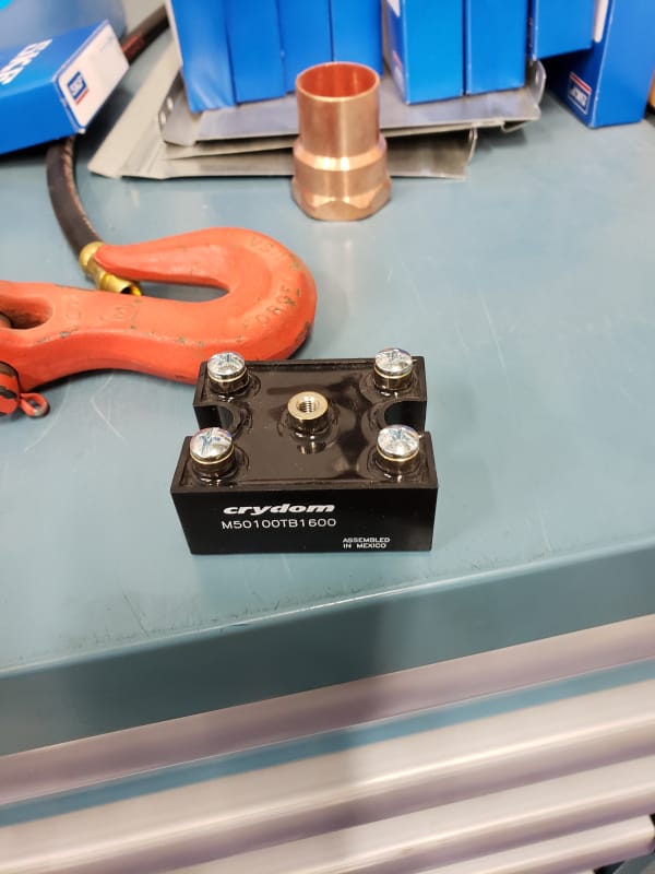
We have replaced the diode pack 2 times with an aftermarket diode pack and once with the CAT OEM part. The persons are doing the work have many years experience, so the packs are being installed correctly. I've attached a pic of aftermarket pack.

We have meggered the rotor and tests okay.

I'll keep you posted and again thanks for the suggestions. JC

Diode_6_pack_wduxqz.jpg


rotor_jumpers_front_3512_1200_rpm_csvi7z.jpg
 
Status
Not open for further replies.

Part and Inventory Search

Sponsor