Continue to Site

Eng-Tips is the largest engineering community on the Internet

Intelligent Work Forums for Engineering Professionals

  • Congratulations KootK on being selected by the Eng-Tips community for having the most helpful posts in the forums last week. Way to Go!

Field Measurement of Roof Spread

Status
Not open for further replies.

northernoutpost

Structural
Sep 28, 2011
3
I need to periodically measure/monitor the roof/walls of a 150 year old church for lateral movement (spread), over time (possibly for years). The walls are stone masonry and the roof is framed with timber trusses that appear to have had some modifications at some time in the past. The stone masonry at the top of the walls has reportedly been repaired a number of times over the years, to deal with spreading of the eaves. There is no written documentation or drawings for anything in this building. The eaves are at least 20' above the sanctuary floor. While measuring/monitoring could probably be accomplished internally or externally via conventional survey equipment, it seemed to me that there must be modern digital equipment available to put in place for such a purpose, leave in place, and periodically download data to a laptop etc. I looked on the web and found some info on extensometers with data loggers and linear resistance wire rotary potentiometers, but no detailed info on this equipment for new users, or any way to purchase it. This would seem to be something that a university's structural research lab would be using with regularity. I'm thinking that a wire across the sanctuary, at eave height, tied to one of these devices, would allow measuring and recording of the movement of the roof/walls (via extension or shortening of the wire) vs date etc.

Anybody got some advice on specific equipment to accomplish this task, cost of such equipment, and how/where to procure ?

Thanks.
 
Replies continue below

Recommended for you

Has anyone crawled above the ceiling to examine the structure? It is my experience that some of these churches in the 100 to 200 year old vintage may have been built by barn builders. I have examined some structures that had some wood joints that were spreading.

Sorry, I cannot help on recommendations for equipment.
 
I once had to measure the deflection of a large corrugated pipe used as a pedestrian underpass for a rail road crossing over it as rail traffic crossed over the site.. I used the dial gauges as used for laboratory strain testing of materials with a 2" measuring range and at least 1/1000 inch precision. I attached these to a telescoping arrangement of electrical conduit tubing, one fitting inside the other. At each measuring point I installed reference places made by leaving a drill hole impression in the device, usually a steel rod about an inch diam.. At the ends of this "adjustable length measuring pole" I installed cone shaped points to fit in the 1" diam-rod reference points with the drill hole indent.

For your job and a wire, I'd expect you need to calibrate the wire for temperature and pull force, but at each end some form or fitting that end to the reference system would be needed and of course reading the dial gauge. If a telescoping tube thing (as I used) is at one end, you need a way for adjusting it in 2 inch steps, as with holes at 2" spaces.

It may be that current land surveying devices can be used sending a light beam to a mirror. I'd contact a surveyor that may have such equipment with very good precision. I'd want to be able to read to thousandths of an inch, maybe you could get by with less precision.

I'd also ask about setting up similar surveying equipment outside and just keep track of movements outside. The least one might do is set up a transit some distance away, but on line with the roof edge and using a reference 'line' on the ground to read changes in angles of shots at points on the eaves. A little trig and you should get what you are looking for.

Consider a second, back-up system in case the main one fails. Install some hooks outside on the eaves with no interfering bush, structure below. In a still night, attach a plumb bob to a hook with sufficient strung to reach ground, On the ground have a reference system that is permanent so the plum bob readings can then measure movement. A tree trimmer's basket lift might be handy for doing this.
 
northernoutpost said:
Anybody got some advice on specific equipment to accomplish this task, cost of such equipment, and how/where to procure ?

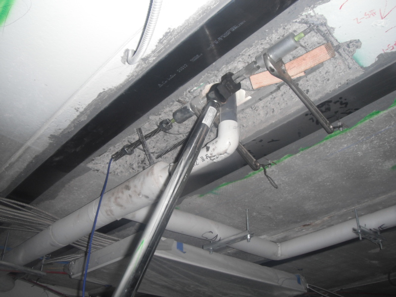
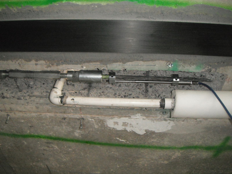
I have purchased and used GEOKON [Link] digital instrumentation. I recently had to measure strain in a bare prestressing strand over a short 8" gauge length, so I purchased a vibrating-wire digital strandmeter (a displacement transducer) [Link] from Geokon with a 4-channel data logger. It was less than $2k, including the PC-based software. With the data logger [Link] and software [Link] you can vary the reading frequency (several times per second, several per day etc).

Geokon also have a wireless option to a datalogger that I believe enables you to remotely monitor the data.

The software is very simple to setup, and the datalogger did not require a EE degree. It took me about 1 hour to setup and start collecting data.

Geokon have excellent customer service and outstanding products. My contact persons at Geokon is Brian Brown. It is worth a call to one of their tech specialists to see what is applicable and affordable for your situation.
 
Ingenuity... you have all the neat toys.

Link saved...

Dik
 
dik:

This is pretty cool technology - easy to use and inexpensive and therefore not just for university research and materials testing labs.

It was by necessity that we purchased the equipment for a project. A GC cored through pretensioning strands to several precast planks and when you use GRABB-IT strand-splice devices [Link] the manufacturer has a recommended torque be applied via a calibrated torque wrench, with a chart that correlates torque to pretension. We were not satisfied with such a manner of determining the magnitude of stressing force so we opted for the vibrating-wire 'strandmeter' that was installed before/during/after the torque was applied. We also used the 'strandmeter' to then monitor the 'strain' relaxation over 24 hours to see if there was any end-slip. The datalogger is able to store data without being hooked up to a PC so we enclosed the datalogger in a Pelican case and secured it with a padlock to keep construction personnel away from the electronics - then after 24 hours hooked up the PC to the logger and grabbed the data. The logger also records strain and temp for each time record.

I just checked the purchase invoice. Total price for VW strandmeter, 4-channel datalogger, USB and all cable connections and software was US$1,800. Early 2016 purchase.

DSCF0843_w9xmno.jpg


DSCF0902_vxceqj.jpg
 
Playing Devil's Advocate here... What is the purpose of the monitoring? What if this collapses under a good snow while you are monitoring it?
 
Is the intent to have semi-permanent, unattended instrumentation? Otherwise, you could get something like this which is a laser rangefinder with about 2mm repeatability. You could set up some defined targets, and make the measurements and look for changes.

TTFN (ta ta for now)
I can do absolutely anything. I'm an expert! faq731-376 forum1529 Entire Forum list
 
We are monitoring the heave of a floor slab using a 3D laser scanner. We have also created as-builts of a 100'-0"+ tall grain elevator that was being re-sided. This technology is becoming more common. How well this would work will depend on your access, visibility of the structure, and the amount of mech/elec items affixed to the wall. The one downside of this technology is the quantity of data collected. We are routinely working with 20million + points of data. It collects the data fast, but the post processing can take a bit of time.
 
Hi,

At universities, for fancy experiments with funding, you use LVDT's and strain gauges, typically. I did some tests on SFRC beams and all I can say is stay away from them if you are on a hurry. LVDT's need to be calibrated constantly since their displacement to voltage relation changes with temperature, humidity or whatever (typically, maybe some equipment don't). You also need equipment to log and software to manipulate this data, and this is expensive and time consuming to understand. If you aren't an expert (say a lab researcher) it will be difficult.

So I suggest the following (up to you if you take the advice):

Use a traditional Dial gauge, which is a mechanical instrument with reasonable precision (0.01mm I believe) and very inexpensive, which is also used in some labs (in mine, when I was a student, geotechs used them a lot, their tests where lengthy and LVDT's typically give you too much information to handle).

And then monitor the dial using a webcam, security cam, or whatever (also very inexpensive). It doesn't sound fancy but it works. You can start your day at the office by taking a look and writing down the value, and more times on the day depending on what your desired sampling rate is. Or maybe program the software to take a picture at different times. I would also maybe place a thermometer and humidity sensor (again, inexpensive) near at the view of the camera as well, you will likely find correlations between deflections, temperature, season, moon phases, and etc.

 
Northernoutpost:
It would really be helpful if we had some photos of the trusses and details, some well proportioned sketches, a cross section through the church with truss layout and pertinent dimensions, etc. Does the truss have a continuous bot. chord, or is it a truss configuration which naturally spreads when loaded? Remember, we can’t see what you are looking at from here. What do the truss joints look like, any relative movement in them, which would indicate outward thrust and movement? What about the truss bearing detail and any evidence of relative movement there? Are the walls plumb, cracked on the inside, or some such? Could you put a tie rod from end to end of the trusses without screwin up the aesthetics too much? You integrate them with some new lighting, etc. and they look like they belong. I would assume you are talking about measuring in 8ths or 16ths of an inch, not .1mm. Could you set a base line and vert. plane, at the base of the wall, and set a laser level to indicate that plane? Then, in concept, fix inward pointing horiz. projecting yard sticks to the top of the wall at/near each truss, at some zero mark, and watch that mark for movement?
 
MonsierR said:
...LVDT's need to be calibrated constantly since their displacement to voltage relation changes with temperature, humidity or whatever (typically, maybe some equipment don't). You also need equipment to log and software to manipulate this data, and this is expensive and time consuming to understand. If you aren't an expert (say a lab researcher) it will be difficult.

Agree. That is the nice thing with vibrating wire (VW) displacement transducers (vs linear potentiameters aka LVDT's) - the output signal of frequency rather than voltage can be transmitted over very very long lengths, without degradation from resistance or temperature etc. And the components are relatively inexpensive and easy to use.

 
@Ingenuity,

Nice to see new technology without the shortcomings of old LVDTs. Still I believe that for the application intended a less elaborated is the way to go.

I forgot to mention you can use photogrammetry, sounds complex but its just using a high resolution camera to track the relative displacements between the camera and the position. You only need to calibrate it once. Precision might not be great, depending on the technique used (DIC, etc.). I still believe a $30 usd dial gauge with a smart way of placing it still and measuring whatever you want(you can use a system of slim cables to help you out) would be the best solution, considering its cost.
 
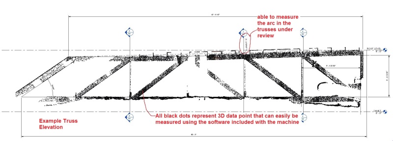
I have included a couple samples from a recent scan of a building we repaired. This is not a long term monitoring assignment, but it seems the most germane to your project. If you have an open ceiling, this is much easier. In this case we were dealing with trusses built in the 40's. Over the years they have crept, and one particular web member was bent beyond belief. The owner in this case was not well funded. The goal of the scan was to confirm if the trusses were plumb, see if other members were bent, and try to determine the cause the movement. In approximately 40min we completed two scans and collected 10 - 20million data points. These were easily imported into Recap and ultimately into CAD software for review. If this were a case where we needed to monitor the building we could do that easily as well, but we would need a surveyor to setup control points.

TRUSS-SECT_hx8zcl.jpg


LONG-SECT_vbyft2.jpg


Pictures would be helpful. Considering the age of the structure, and the type of construction it seems to be a significant asset that the owner wants to save dearly. In that case, the cost does not seem quite as paramount as if this were a structure of low value. Surveyors own this technology, and you can even rent scanners if you choose. You can go onto the 3D laser scanner forum and find any number of companies that do this type of work. We are in a remote location, so we invested in the technology for our own use.

Sorry, pictures not working out very well.
 
One more from OG. In any measuring system be prepared to take readings at different times of day and night as well at differing weather (temp) conditions. You might be surprised to see significant
variations.
 
Status
Not open for further replies.

Part and Inventory Search

Sponsor