Continue to Site

Eng-Tips is the largest engineering community on the Internet

Intelligent Work Forums for Engineering Professionals

  • Congratulations MintJulep on being selected by the Eng-Tips community for having the most helpful posts in the forums last week. Way to Go!

Field Welding Non-Weldable Rebar 2

Status
Not open for further replies.

KootK

Structural
Oct 16, 2001
18,280
Context

- Grade beam on a local infrastructure project. It supports a fence that keeps sabre toothed tigers from eating babies. Low importance factor as with most livestock stuff.

- An unfortunate core has been made through the grade beam top reinforcing.

- Various constraints are making it desirable to get this repair done in as localized a manner a possible. The fence is already in place and its anchorages are nearby to the location where this repair will take place. The repair location is also very close to a plan "corner" where the grade beam changes direction over the pile.

- Quality control on this project is good. You know, other than this ridiculous core.

- One repair option being considered is field welded splices of the reinforcement. This is not weldable rebar, however, so we'd have to deal with preheat.

Questions

How good -- or bad -- of an idea is it to consider field welded reinforcement splices here from a QC perspective?

Is there any danger that the preheated bars would expand and cause the cover concrete of the grade beam to spall?
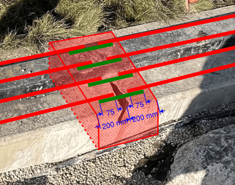
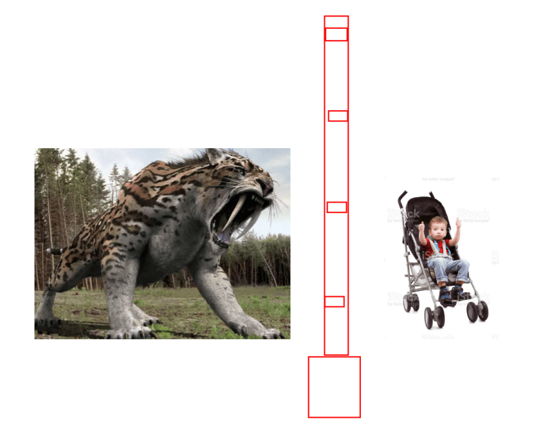
01_cifoau.png


c02_p1jdan.png
 
Replies continue below

Recommended for you

THLS said:
Take a close read of W186. The scope of G30.18 says that all bars are weldable given the right conditions.

Thanks for that. It's solidly answers the "is it at least possible, if not advisable?" part of the question.
 
Are there mechanical couplers that could work here? Maybe if you jacked out a little more concrete? Maybe one of the old school crimping type couplers (which I have not used).
**Wait, apparently I waited too long to post this and the conversation passed me by**

FWIW, I thought of the crimping coupler because I think it tend to have a lower profile and might not cause as much of an issue for cover problems.

KootK said:
What would be awesome is if there were a two piece mechanical coupler that could accommodate the gap. A lot to ask, I know.

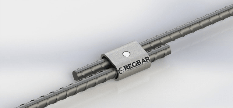
I did a google search and saw a product like this. But, I don't have any experience with it:
side_by_side_coupler_qcga8r.png


You probably better know how to weld to "non weldable" rebar better than I do. I think the issue with welding would primarily be a drop in expected ductility more than anything. Meaning a fracture mechanics issue related to the weld / base material. But, this doesn't look like an application that requires much ductility.
 
I wonder if these manufacturer's have oversized (over-lengthed?) couplers with additional screws, which would allow for the gap in the splice to not be a problem.
 
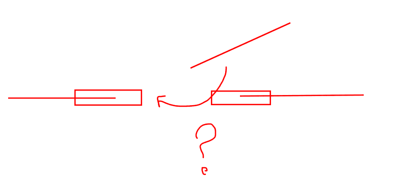
With respect to the sketch below, I see it now. You'd remove enough concrete to slide the sleeves past the existing rebar. Then drop in the new piece and slide the sleeves back to where they need to go.

c01_hkvheh.png
 
KootK said:
Thanks for that. I was just about to summon you to this thread.
Thanks, that just made my weekend.

KootK said:
Quote (THLS)
Take a close read of W186. The scope of G30.18 says that all bars are weldable given the right conditions.

Thanks for that. It's solidly answers the "is it at least possible, if not advisable?" part of the question.
If we are talking ASTM A615 rebar it is "weldable" all day long. The only difference is the higher preheat that is required. Having mill certs could help as you can calculate the actual carbon equivalency to determine your lowest preheat but honestly, just assuming worst case per D1.4, the required preheat is still only 300°F for #6 and lower or 500°for #7 and higher.

D1.4 says this in concern to spalling due to heat:
D1.4_fxpppb.jpg

Which isn't very helpful as it doesn't give any guidance.

You could always experiment with preheating the end of a loose bar and measure temperatures further away to see if it is something you are comfortable with. My intuition/gut (which is based on nothing) says anything under 200°F isn't going to cause an issue. I would think issues would tend to arise very quickly as soon as you start "boiling" any moisture in the concrete - that would probably have a much greater effect than the thermal expansion of the steel.
 
Tough one.

Nothing I can think of makes this work internally without doing something weird and using a product outside of it's design intent

But if you're down for that...

-Chip around the end of each cut bar roughly 3"
-Install a BarSplice FITT on each cut end
-Insert a cut length of larger diameter weldable bar flush to the inner (core-side) face of the FITT
-Weld the weldable bar to the FITT

 
JoshPlumSE said:
I did a google search and saw a product like this. But, I don't have any experience with it.

That's not bad actually. Those things don't take up much space in any direction. If they've got ESR reports, that's good enough for me.
 
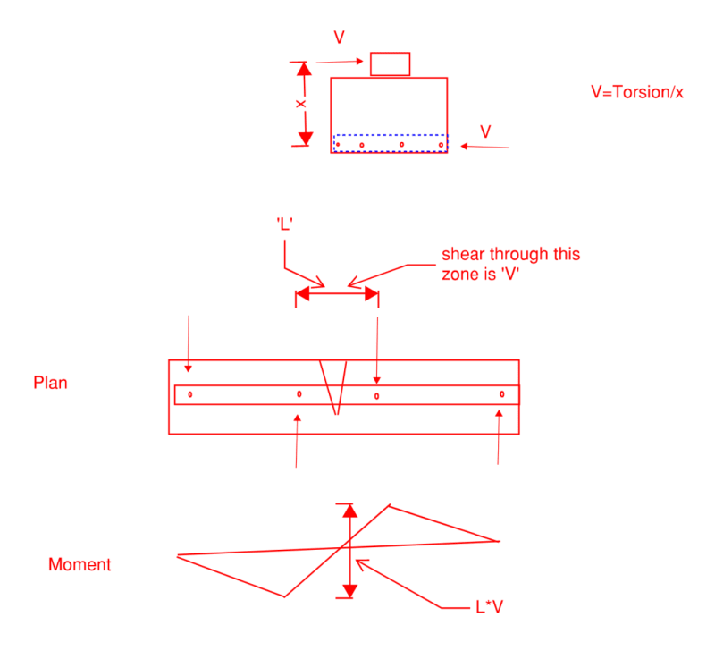
I don't think my wacky torsion idea is a first tier solution, but depending on the load, the deflection may not have an insane compatibility issue given the small span. Issues relating to bolt slop would need to be worked out, though. I think I see unusual torsion load paths in my sleep at this point. Industrial stuff always has some weird torsion load that isn't necessarily big but still needs to end up somewhere.

Screenshot_2023-09-01_122109_hrvfxw.png
 
SwinnyGG said:
But if you're down for that...

Thanks. I'll put you down as a contender for the polka dot jersey as well.

c01_y2943s.png
 
On the topic of weld based spalling. If the plan allows chipping out as required anyway as part of the repair I would suggest that it doesn't really matter if you can't analyze the extent of it. If you get a spall in those first couple of feet where there's high heat, chip it out and include it in the repair zone.
 
The Bluebeam photoshop work on this thread deserves an award on it's own - laughed out loud multiple times today
 
how about adding a helical pier right there with underpinning bracket?
 
KootK said:
That's not bad actually. Those things don't take up much space in any direction. If they've got ESR reports, that's good enough for me.

Yeah, I have my doubts. Outside of those pictures the manufacturer doesn't talk about them much. But, I'm sure you could talk with a technical representative about them.

Heck, even if they don't have ESR's it might be a solution. It's not like welding the rebar would be a great solution either. Either way, you're dealing with something that's a bit outside of "standard practice".

 
Luceid said:
The Bluebeam photoshop work on this thread deserves an award on it's own - laughed out loud multiple times today

Thanks. One catches more bees with honey, right? And it is long weekend Friday...

Before there was Bluebeam, there was only the void.

Base file in case anyone else feels compelled to digress: Link

c01_lclpwx.png
 
Lenton Quick Wedge Is likely something you can find relatively easily in Canada. I would likely be inclined to weld.
 
Metallurgical and CE testing? or call on a testing lab to provide the information.

-----*****-----
So strange to see the singularity approaching while the entire planet is rapidly turning into a hellscape. -John Coates

-Dik
 
Back in my days in the nuclear power industry, there were Cadwelds. Since you couldn't lap splice #14 and #18 bars, they would be cadwelded. But don't worry, they make them in smaller sizes, too. Plus, they had to test 10% of them. To do that, they'd cut out a splice and send it to the lab. To repair the missing splice, they'd have to add two more cadwelds.
Anyway, they use molten metal to make the splice, so there's sparks and fire all over. Pretty cool.
 
A. Is it possible to cut threads into the rebar end, then thread a weldable nut or coupler on? Then, weld a rod or something to that.

B. If it’s possible to slide a steel tube over both ends of the rebar, fill the tube with epoxy.
 
I'd second the Quick Wedge idea from Brad805 - I was thinking of that type when I found the longer bolt-on type and posted because I didn't have time to keep looking for it.
I've seen similar couplers used on post-tensioning tendons on bridges where concrete bridge girders were coupled together over a pier to produce a continuous span condition.

For this concrete-railing curb thing herein I'd think these types of couplers would do fine.

KootK - I meant 1" clear between couplers. So if you had 11" long couplers you'd have an 11" coupler - then 1" gap - then 11" coupler....using a 12" long bar piece in between the existing embedded bars.
Total chip-away area would have to be longer, perhaps 36" to allow the couplers to slide fully onto the embedded bars and allow positioning of the center new bar before sliding the couplers back to within 1" of each other.

Brad805's couplers are much smaller so less chipping.


Why can’t you use a coupler like the one I linked to? It’s off to the side, they list dims in there. You’d have to get the side splice bar loaded onto it, slide it over one bar via a gap, then the other. Too much removal for your liking? Otherwise it seems like it works(ish)
 
Status
Not open for further replies.

Part and Inventory Search

Sponsor