Eng-Tips is the largest engineering community on the Internet

Intelligent Work Forums for Engineering Professionals

Figure UG-34 (g)

Status
Not open for further replies.

aard

Mechanical
Mar 1, 2016
26
0
0
US
Hello,
Basically I don't understand the figure UG-34 (g). I am not clear on how is the joint and how should be perform the welding according to figure UG-34 (g).

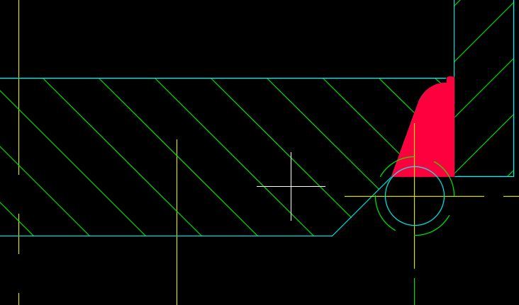
Please check the yellow rectangle on the attachment. Is that a J-type groove? is tw the land? If is the land it looks so big that cannot be physically possible to weld.

Can somebody explain me with an example?

 
Replies continue below

Recommended for you

Appears to be a circular flat head like in (e) and (f) except it is attached by a groove weld rather than fillets. See description in UG-34(d)(6) where it starts with "the size of the weld t_w in sketch (g) shall..."

 
yes, UG-34 (d)(6) says that is attached by groove as shown on the figure but I still don't understand how is that groove. It doesn't seen a regular groove the land seems too big that is not possible to deposit to fill the weld. If you can help me to understand I really would appreciate that hehe
 
Yes land that you see is for a very thick plate that can be left unwelded but there are other rules that govern. Cut your plate at 35-45° and weld per Code.

General Blr. CA,USA
 
We actually just used this detail recently on a job. Attached, please see a screenshot from our drawing (Ignore the circles in the detail, these are for something else...).

We performed the groove weld from the outside only due to access issues. The groove weld however could be completed with just about any prep (single sided v-groove, single sided j-groove, double sided v-groove, double sided j-groove, ...).

The 45° max slope on the unwelded portion comes directly from the figure (UG-34(g)).

Cheers!

Capture_rwrnci.jpg
 
Status
Not open for further replies.
Back
Top