structured
Structural
- May 25, 2012
- 16
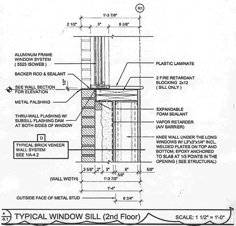
In my office we often specify windows as a delegated design item and have them supported on CFMF walls which are also specified as a delegated design item.
My question for those of you who have similar experience is this; who is responsible for the design of the blocking between the window and the wall? Is it the SSE for the windows, the SSE for the CFMF walls, or the SEOR?
There are arguments for and against each of those options. My instinct is that the SSE for the windows should design it. The way that our specs are written they are already designing the anchorage for the window. We as the SEOR do not want to do it because we don't know for sure what the windows and CFMF are doing until after the submittal process begins. If we start designing blocking at that point it will be a change order for sure. The SSE for the CFMF will almost certainly refuse for similar reasons to us and since timber is not their specialty.
So, what do you think? Is there a standard practice here that I am missing? I've been scouring the codes, MasterSpecs, and industry articles for some guidance but so far have come up short.

