Continue to Site

Eng-Tips is the largest engineering community on the Internet

Intelligent Work Forums for Engineering Professionals

  • Congratulations SSS148 on being selected by the Eng-Tips community for having the most helpful posts in the forums last week. Way to Go!

Finding Deflection of a Steel Beam from a Moment Diagram

Status
Not open for further replies.

LeonhardEuler

Structural
Jun 19, 2017
200
Hello,

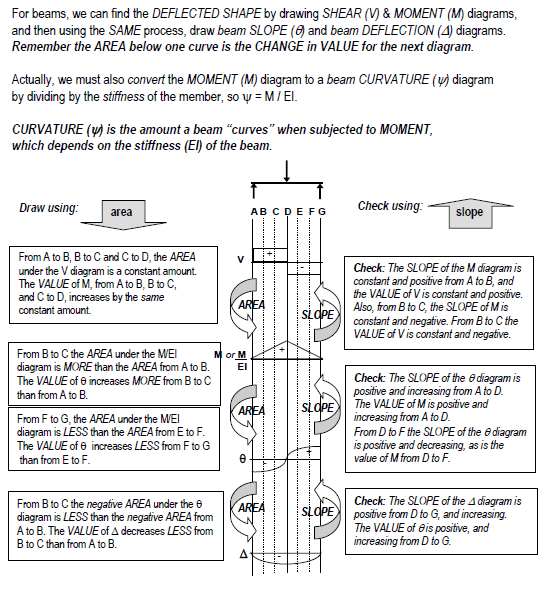
Is there an easy way to find a deflection diagram from a moment diagram such as what is given in Risa.

I am attempting now and this is what I have come up with.

1) Plot the Risa moment diagram into excel, with the x-axis being distance, and the y axis being M/EI and use a best fit line to develop the equation of the line. This should be the angle of rotation if im not mistaken
2) Solve an indefinite integral of the angle of equation formula in terms of x, which will give the equation for deflection.
3) Plot the equation from the indefinite integral of the angle of rotation equation and you will now have the deflection equation.

There is something wrong in this project as I am getting a deflection diagram that doesn't resemble Risa's
 
Replies continue below

Recommended for you

If you are using RISA, it will give you the deflection.

If you want to verify w/ hand calcs, "load" your beam with the moment diagram, and calculate the "shear" where you want to calculate the deflection.
 
How do you find shear for such an irregularly shaped loading as you may find in a moment diagram.
 
Take the profile of your moment diagram and apply it to your beam as if it were a continuous load (with units such as lb/ft). Then simply calculate the shear based on that load and that will be your deflection/EI. Google "Moment Area Method" for beam deflection.
 
So it sounds like I would need to find the area under the moment diagram for this, which is why I was integrating the M/EI formula to find area. Once I find the area I can put an equivalent uniformly distributed load across the beam and solve for max shear?
 
MotorCityI think what you are referring to is the conjugate beam method.

I guess what I am asking here is once I have the equation of the moment diagram is there an easy relation such as ∫∫M/EI dx is equal to the deflection at any point along the beams length.
 
My memory of this is a bit fuzzy, but first integral of the M/EI diagram gets you slope, the integral of a slope diagram gets you deflection. Screenshot of my analysis course attached.

image_kt9fsh.png
 
Jayrod12 is correct. Load the conjugate beam with the M/EI curve. Shear of the conjugate beam is the slope of the real beam. Moment of the conjugate beam is the deflection of the real beam.

A simple example:

Consider a beam with equal and opposite moment 'M' applied at each end (cylindrical bending). Moment diagram is constant M across the entire span. M/EI is also constant across the span. Shear at midspan of conjugate beam is zero which means that slope in the real beam is zero. Maximum moment at midspan of conjugate beam is (M/EI)L2/8 so maximum deflection in the real beam is (M/EI)L2/8.

BA
 
Ahh, yes......my error (had to blow the dust of my structural analysis book). The SHEAR gives you the slope and the MOMENT gives you the deflection.
 
if you have all your applied loads (as discrete and distributed forces),
and if you have your end reactions (from RISA ?) else solve by hand.
maybe you can simplify as a UDL across the span

then calculate where you have zero shear (where in the beam does the applied load balance the end reaction);
for full-span UDL it is (obviously) the mid-span.
This is the point of max deflection.

So now you have the shear diagram for either 1/2 of the beam.
calculate the area under it (piecewise, between loads) for the moment
then calculate the area under the moment curve, divide by EI and this gives you slope
then calculate the area under the slope/EI curve, this gives deflection.

another day in paradise, or is paradise one day closer ?
 
BAretired Thank you very much I see that this is a viable option to find deflection, but my particular case has a quadratic moment diagram. I think this would be very hard to calculate a moment and shear using a quadratic load. I was looking for a way to use pure math such as integration, but perhaps there isn't such a simple method.
 
I think your moment diagram should be simple functions describing portions of the overall curve.
Simple functions should be easy to integrate.

btw if the moment is quadratic, then the shear is a linear load.

another day in paradise, or is paradise one day closer ?
 
"I was looking for a way to use pure math such as integration, but perhaps there isn't such a simple method."

Integrating the moment equation twice is the mathematical solution, but depending on the the complexity of the moment equation, it may not simple at all.

You should be able to approximate the RISA solution using an incremental approach in Excel (a Reiman sum).
 
I don't think quadratic functions are particularly difficult to integrate, but when the moment diagram is too difficult to integrate, you can use numerical integration such as Newmark's Numerical Method. It is perfectly adequate for most engineering problems. I have used it on many occasions.

The method entails dividing the span into several sections, usually four, six or more. If the moment at each point is known, an equivalent concentrated load is calculated for each node. When the moment equation involves second, third or fourth order equations, Newmark used a second order approximation to determine equivalent loads.


BA
 
I'm a bit puzzled why you find a problem calculating the shear and moment when you are happy integrating a curve, but a mathematical procedure that will do what you want is:

1. Assume zero slope at one end, and integrate the M/EI curve to find the slope curve.
2. Integrate the slope curve to find the deflection curve.
3. Rotate the deflection curve so that the deflection at end 2 is zero. This is the actual deflection curve (assuming a single span with no deflection at the ends).

This procedure is equivalent to the conjugate beam method.

Macaulay's method is useful for simplifying the coding for partial and point loads. My Conbeam spreadsheet has open source code, applying this procedure to single span and continuous beams:
background information:

Latest version:


Doug Jenkins
Interactive Design Services
 
HotRod10I did a double integral in Mathcad of M/EI, where M was a quadratic in terms of x and plotted the result along the beam length, but got an answer that was no where close to what Risa got, or what I approximated with Table 3-23 beam forumulas. Should it just be a double integral of M and not M/EI? Maybe I just flubbed some numbers.

IDS I suppose I should have no problem finding the shear and moment from a quadratic loading if I take the time to actually get some paper and pencil out. I suppose the conjugate beam shear would be cubic and the moment would be ^4. It's likely not as hard as i'm initially making it and I should know to always start solving on paper first.

IDS said:
1. Assume zero slope at one end, and integrate the M/EI curve to find the slope curve.
2. Integrate the slope curve to find the deflection curve.
3. Rotate the deflection curve so that the deflection at end 2 is zero. This is the actual deflection curve (assuming a single span with no deflection at the ends).

Forgive the question, but these are indefinite integrals correct? This is the exact method I followed, but received an answer that was off by a factor of ~100. I guess I must have simply entered something into my file wrong.
 
Forgive the question, but these are indefinite integrals correct? This is the exact method I followed, but received an answer that was off by a factor of ~100. I guess I must have simply entered something into my file wrong.

Assuming zero slope at end 1 makes it a definite integral, then rotating to give zero deflection at end 2 corrects the results for the actual end 1 slope.

Could it just be a units problem?

Doug Jenkins
Interactive Design Services
 
IDS said:
Assuming zero slope at end 1 makes it a definite integral, then rotating to give zero deflection at end 2 corrects the results for the actual end 1 slope.

Could it just be a units problem?

According to this my issue is that I did a double indefinite integral when I should have calculated an integral going from what I assume to be 0 to x. I am sure my error is somewhere in the integration process.
For example my M equation after dividing all moments by EI was -1.2x^2+0.3x+4... so to find deflection I did... ∫∫(-1.2x^2+0.3x+4)dxdx with both integrals being indefinite, but it sounds like I should have done

something of this nature 0tox∫0tox∫(-1.2x^2+0.3x+4)dxdx?
 
Status
Not open for further replies.

Part and Inventory Search

Sponsor