Continue to Site

Eng-Tips is the largest engineering community on the Internet

Intelligent Work Forums for Engineering Professionals

  • Congratulations KootK on being selected by the Eng-Tips community for having the most helpful posts in the forums last week. Way to Go!

Finding most critical condition for 10" CS pipe with several design conditions

Status
Not open for further replies.

Vrod76

Mechanical
Oct 27, 2005
7
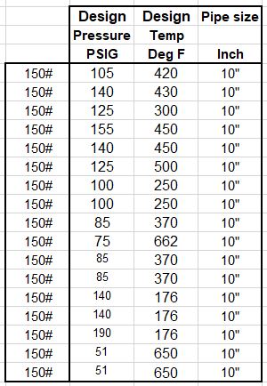
Hi, I have a Piping line list with various design conditions. Say, For carbon steel material 150#, 10"pipe, there are various pressure and temperatures. Should I calculate the pipe wall thk for each condition as per ASME B31.3. Or is there a shorter way? How to arrive at the most most critical service and generalise it to the entire selection? Pls have a look at the file attached for reference
Capture_eupfzc.jpg

 
Replies continue below

Recommended for you

As these lines are under the piping of Class 150#, the pipe wall thickness may be calculated per max pressure of the 150# Class based on B16.5. And, it should be adequate for all the pressure/temperature conditions of the lines as listed.
 
Highest pressure at highest temp.

So I would go for 155psi @ 450F

Check 125@ 500 and 75 at 662F

Material type makes a big difference.

Check flange rating as well.

Be careful what people mean by #150. As you have a design pressure this takes precedence over the maximum pressure available from a flange rating at a certain temperature. Taking the max pressure from the flange class rating might be conservative and result in thicker pipe than you need.

Remember - More details = better answers
Also: If you get a response it's polite to respond to it.
 
Seems like you have a computer, so why not check every one of them.
How difficult is copy and paste?

--Einstein gave the same test to students every year. When asked why he would do something like that, "Because the answers had changed."
 
kuldeep76 said:
Should I calculate the pipe wall thk for each condition as per ASME B31.3. Or is there a shorter way?

Code requirement is defined in 301.2.1(c):
When more than one set of pressure–temperature
conditions exist for a piping system, the conditions
governing the rating of components conforming to
listed standards may differ from the conditions governing
the rating of components designed in accordance with
para. 304.

Short; without proper assessment of all individual combinations, you cant really tell which one is the prevailing combination and thus your design condition.

Huub
- You never get what you expect, you only get what you inspect.
 
Op,
The most severe condition will be that which will result in the highest thickness of the pipe.
Start a spreadsheet and calculate thickness for each design conditions.
That being said, the condition governing the component rating (example flanges, valves etc) may differ to the design condition for the pipe.

GDD
Canada
 
Hi XL83NL, I agree with you. I had come across a PT calculation excel sheet at my workplace.
In there we can assign any random thk to the entire size range of CS pipes falling in the project
Say...
1/2" to 1 1/2" 80SCH
2" to 8" 40SCH
10" to 24" 20sch
above 24" as per line operating conditions

This sheet, strips off the Mill tol and Corrosion allowance from the pipe wall thk.
This wall thk is used in the MAWP formula (as per ASME B31.3) to verify by back calculation if the value thus found, exceeds the rating MAWP as per ASME B16.5
All we have to do is keep reducing the pipe schdules to the point of tip over. IE. the calculated MAWP gets lesser than the flange rated MAWP, which means we have reached the failure point. So we go the the next higher thk and finalise the design. What's your call on this kind of working?

However if the calculation is to be done the usual way by calc the thk and then chking against the MAWP then is would be cumbersome.
Not sure how would it look like. So ...my question if there is a way to point out the worst case !!!
But yes I would be certainly more comfortable to check all the design conditions the line would have to face before passing it.

Thanks all for your help
 
So what's the point of specifying the design pressure if you're not going to use it??

Or your way, there is class 150 MAWP for each temperature, just plug that into the walk thickness calculation in B31.3, noting that the S value for your pipe material might change due to temperature as well.

This is all very intern level here....

Remember - More details = better answers
Also: If you get a response it's polite to respond to it.
 
Hi GD2
You said - the condition governing the component rating (example flanges, valves etc) may differ to the design condition for the pipe.
By this do you mean I should back calculate the MAWP using the Allowable stress values from ASME B31.3 Table A-1 - For all components like Pipe, flange, castings and wrought fittings??
Usually we check just for pipes and fittings. Forged items and casting have a higher value of Allowable stress in comparison, at least for Carbon steel material.
So I must guess castings and forging can be kept out of calculation conveniently. Correct?
 
Yes

--Einstein gave the same test to students every year. When asked why he would do something like that, "Because the answers had changed."
 
The worst case of the pipe wall thickness calculation is to be based on the pressure conditions of B16.5 Classes, i.e. 150#, 300#, etc., for the specific material.
Typically, the casting fittings are specified with the pipe wall thicknesses, and the forged fittings are selected either 3000#, 6000#, or 9000# ratings per related pipe wall thicknesses.
 
Hi LittleInch
You said-So what's the point of specifying the design pressure if you're not going to use it??

Are you assuming that Thk calc here, is being considered without the design parameters?

As per the method we start with a random wall thk and go on reducing it. This is done till the Calced MAWP is just above the flange rated MAWP. The MAWP thus calculated has the allowable stress component which is in proportion to the design temp. The value hence obtained must be greater than the MAWP as per 16.5. This mawp also is in proportion with temperature.

So the design pressure and temperature is factored in for calc of thk. Wouldn't you agree?

You also said - Highest pressure at highest temp.

Kindly look again at the line list. For highest pressure the temperature is lower and for the highest temp conditions the pressure is lower. No single condition that fits all.

Hence I find going tru all the service conditions is the best bet in making the system fool proof as suggested by another member of this forum. Pls correct me if I'm wrong
 
kuldeep,

You don't seem to be understanding what I'm saying so no I don't agree with this backwards method you're proposing.

Normal method is chose a design pressure to use at a certain temperature then work out the thickness and choose the next standard wall thickness in ASME B 36.10. Simple.

The issue is what pressure do you choose to use.

You list a set of "Design Pressures", but then seme to ignore it in place of the MAWP able to be used according to ASME B16.5 flange rating. This number is available from the design temperature being used.

So no need for this trial and error system.

Your OP started by asking which ones to choose. I admit I didn't see the 195@ 176, which should be one to look at.

Is this is the same pipe but subject to different conditions or you just want to buy one thickness of pipe which covers all situations?

Remember - More details = better answers
Also: If you get a response it's polite to respond to it.
 
OP,
You said you had created the table from Line List.
Looks like the lines are picked from different systems with different operating conditions and, therefore, different Design conditions. Or does one line sees all the variations of P/T? If the later is true, your question to determine the most severe/critical design condition is valid, otherwise not.
The design condition will be the one that will give the highest pipe wall thickness after evaluating all the operating conditions (pressure/temperature combinations).


GDD
Canada
 
In the line list, different lines see different design conditions. For CS moc alone design temp below 650Deg F there are over 100 entries for different pipe sizes. It's certain that the condition giving the highest wall thk will be the worst condition. But there should be a method wherein we can find the worst condition and apply it to the entire size range of pipes.
 
Only if you have a lot of money.

Why buy pipe thicker than you need to?

Now tbf, there is value in only having say three or four thickness of pipe to avoid too many and lengths make a difference as well.

If the high pressure high temp stuff is only 30m,but you have 5000m of lower pressure stuff, why buy all that thick pipe when the majority you need is thinner??

Remember - More details = better answers
Also: If you get a response it's polite to respond to it.
 
OP,
The intent of the Line List is to identify each line with all its properties of P/T, operating/design conditions, insulation/tracing, expansion temp, test type, test pressure etc.
I guess what you want to draw from the Line List is the 'Piping Class', where pipings are grouped by service and P/T range. Example: water service, Class 150, Class 300 etc. (limited by flange ratings).

The Line List should have the 'Piping Class' designator in the line number.

GDD
Canada
 
I guess what you want to draw from the Line List is the 'Piping Class', where pipings are grouped by service and P/T range
Yes GD2
The line list I posted at the start of the thread is for the service categorised as "D category" fluids. These have the PT range suitable for 150# class. I've just posted the entries filtered out for size 10" pipes alone (for being concise). The entire sheet has sizes varying from 1/2" to 24". So there are numerous combination of P vs T for just this one class.

If I must find the max thickness out of all these conditions then I shd get busy arranging all the temperature values on the excel sheet and feeding the interpolated allowable stresses from 31.3 & interpolated MAWP from 16.5 against each temperature entry. That's how I get the max thk in some entry that gets calculated.

In a template provided for this activity, I see a design condition picked randomly out of the bunch of PT combinations of a certain service and considered as the worst condition. Based on this chosen condition the all pipe size thks are calculated. Dunno how they arrived at this condition?? For trial, I tried using other combinations of PT to see if I get thicker values, but alas it is calculated to be thinner. There is a way to zero in on the worst PT condition, without going all the above process, which seems to elude me.

Now I've to develop spread sheet (@ 25 or above) based on the brut force method OR hitting the hammer once at the right place to get the entire ship's engine to roar back to life.

Any help on this would be very useful.
 
Only if you have a lot of money. Why buy pipe thicker than you need to?

Yes LittleInch
Your ans is justifiable. Nobody would buy higher thks unnecessarily. But there is another aspect where you need to keep the inventry as trimmed as possible else that are lot more challenges in store.
A pipe class is defined which included various services. Some services OR PT combinations do not require the selected pipe thk yet we add them into one pipe class so that the variety of pipes are in control.

Now 150# & 300# pipe classes contains max of the pipes. If they are to be broken down PT wise then we would end up with 20 separate thk sets(or more). The probability of mix-up happening at the site during construction greatly increases. So for that reason we generalise and keep a few services within one Pipe spec or pipe class (which may be over designed for some services and PT combinations).

This is what I could come up with my limited knowledge & experience. Pls correct me if I'm wrong.
 
I think you're correct. You do sometimes see a varient so pipe clas 15D1 and 15D2, but the issue of keeping multiple different pipes and mixing them up can be more important.

As fir choosing the right one to use to determine the worst car m case is a bit of experience and familiarity with the B31.3 code and knowing where materials start to drop in S value.

Pressure though is usually your key parameter.

Remember - More details = better answers
Also: If you get a response it's polite to respond to it.
 
Status
Not open for further replies.

Part and Inventory Search

Sponsor