Eng-Tips is the largest engineering community on the Internet

Intelligent Work Forums for Engineering Professionals

  • Congratulations waross on being selected by the Tek-Tips community for having the most helpful posts in the forums last week. Way to Go!

Finding stress on plate

Status
Not open for further replies.

EHhpprocess

Mechanical
Mar 25, 2024
3
0
1
US
Hello,

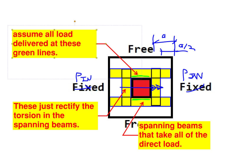
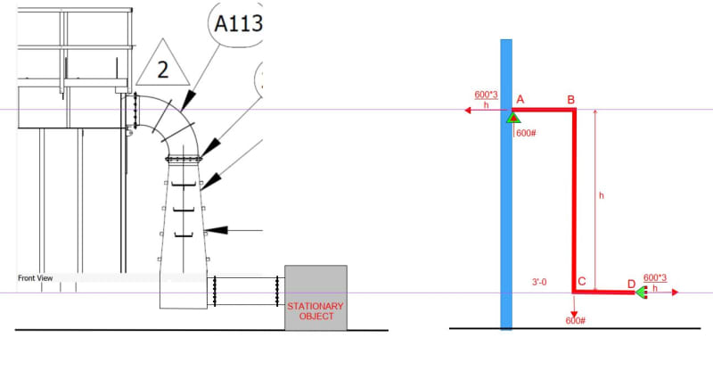
I'm having some trouble determining the max stress on a sheet metal wall with ducting hanging off of it. I've attached a png of what I'm working with. The red square is the hole in the plate where the top and bottom of the plate can move freely and the two sides are rigidly held in place. There is a moment created on the x-axis from the weight of the duct hanging off the sheet metal wall.

Is there a general equation to find the max stress? looked through Roark's and haven't found something that resembles what is occurring. I don't have access to FEA software.

My thought was to treat this as a beam between two rigid supports with a moment along its long axis, but I'm not confident that I'm conservatively estimating the loading on the plate.

 
 https://files.engineering.com/getfile.aspx?folder=8801db23-96c3-4784-861c-f82f5947f6e2&file=Plate_sketch.png
Replies continue below

Recommended for you

You could use some free FEA software like CalculiX. There are even nice graphical preprocessors for it so you don’t have to struggle with solver files.
 
Not sure I understand the situation. Is the figure a plan or elevation view? In other words, are X and Y horizontal, with Z pointing up? What direction is the load?

If X and Y are horizontal then I agree with BAretired - use yield line analysis to compute the strength.

That does not check deflection, though, so you'll need some way to check that. Either FEA or idealize the plate as a beam and compute an approximate deflection.
 
I would think there are a few ways this problem could be simplified. First suggestion is to cut the plate into four segments, along lines joining the corners (e.g, top left outer to top left inner). The top and bottom segments will be in bending, fixed at inner box edges? The side segments in twist, with equal gradients at the inner box. You can work out the bending and twisting stiffnesses and proportion the moment applied in the middle. Once proportioned, work out the stresses in the top and bottom segments. Food for thought!
 
I'd just discretize it like this unless there are 10,000 of these things or its an existing condition.

Kind of like an RTU support frame.

c01_b59mfb.jpg
 
I can run it for you (if you want). But I'd have to know a lot more, including:

1. Loads (and how they are applied)
2. Material & thickness.
3. Which way is up (like 271828 was talking about).
4. Dimensions.

And keep in mind: what I will give you will include a lot of stress concentrations.

Kootk had a pretty good suggestion.
 
Thank you all for responding so quickly. I should have given you the actual problem I'm facing and not just how I simplified it. I have a bag house with ducting hanging off of it. The weight of the duct is ~600lbs and its COG from the wall of the BH is ~3ft. The hole for the outlet ducting is 18'' in height and 112'' in width. The plate from the hole to the supports and edges of the plate (fixed and free ends in my rough sketch) is 16'' on all sides.

The actual problem is that the previous engineer working on this job didn't add a flex connection between the ducting and the baghouse so the weight of the ducting will be supported by the wall of the BH. And the foundation has already been poured so I can't just move any part of the system to account for the flex connection. I need to determine if the stress from the ducting hanging on the BH could cause an issue, specifically if the BH needs to be strengthened around that connection. I'm going to add a flex at the bottom of A113 and the next duct and then rigidly support it so I wont have issues there, but I can't rigidly support A113 itself because of thermal expansion as the system starts up and is shut down. A113 is the item number for the duct in the pictures I've attached to this reply.

In my rough sketch Y is vertical, going up normal to ground.

Here are the images taken from GA drawings. A113 is the duct in question.
Top View
Top_view_of_BH_hctuvb.png

Side View
Side_view_of_BH_u2nyun.png

Front View
Front_view_of_BH_ovl1w1.png
 
Thank you, WARose, for the offer. I'll wait on that because I feel like this is more of me being naive than not having access to FEA software. Nonetheless thank you!

BAretired, I'll look into that.

FEA way, that some pretty cool software. I'll have to talk to my IT and see if I can download it.

KootK, I like your idealization of the problem. I can play around with how that should work.
 
I'd break it down similar to Koot.
Same idea as a one way slab with an opening, rough check - if it passes call it done.

A sketch of the situation would be helpful (in particular the part with the support hanging off the wall).

 
I'm not convinced that you have the correct static model. Your SIDE VIEW does not show what happens at the bottom of the duct. If the duct is supported (or could be supported) at the bottom, it is possible that the sheet metal support for A113 does not resist a moment. In other words, the joint at the wall could be a nominal connection which may act as a pin, possibly supporting a vertical load but no moment.

Please indicate the full SIDE VIEW all the way down to the floor.
 
Expanding on yesterday's comment, I believe the sketch at left represents the structure. The sketch at right shows a hinge at A and D, the applied load of 600#, and the reactions at A and vertical roller at D. Notice that there is no moment at point A, provided point D is prevented from moving horizontally and the duct ABCD can be considered a rigid element.

Capture_t94wj6.jpg
 
In Fig. 1, 2 and 3, the Z-shaped duct spans as a beam from one unit to the other. In Fig. 4, the duct is much larger and heavier, so it rests on the floor. In all cases, the moment at each end of the duct is small if the supports are flexible.

My preference is to let ducts do what ducts are meant to do, confine dusty air, not act as beams. A 600# weight seems a bit much to be carried by duct-work; I suggest supporting the load on the floor, similar to Fig. 4. Duct ends should be connected to prevent leakage; pin supports are best, and they do not stress any plates in bending.

Capture_ztziw0.jpg
 
Status
Not open for further replies.
Back
Top