Continue to Site

Eng-Tips is the largest engineering community on the Internet

Intelligent Work Forums for Engineering Professionals

  • Congratulations KootK on being selected by the Eng-Tips community for having the most helpful posts in the forums last week. Way to Go!

Finding the deflection of a deep beam with 2 point symmetric loading 2

Status
Not open for further replies.

Chris2448

Civil/Environmental
Sep 16, 2020
2
Hi,

After researching I found a formula by Timoshenko (1957) and Burland and Wroth (1974) deflection of a central load on a deep beam. I'm wondering if there is a similar style formula for a symmetric two point loading on a deep beam which calculates the deflection?

Would appreciate all the help!
 
Replies continue below

Recommended for you

There could have solved equation for such case, you have to look around. But in general, Timoshenko beam theory takes into account of shear deformation, the differential equation of total deflection is:

d[sup]2[/sup]v/d[sub]x[/sub][sup]2[/sup] = d[sup]2[/sup]v[sub]b[/sub]/d[sub]x[sup]2[/sup][/sub] + d[sup]2[/sup]v[sub]s[/sub]/d[sub]x[/sub][sup]2[/sup], in which v[sub]b[/sub] and vs are deflections due to bending and shear respectively.
 
can the Timoshenko equations be modified for a point load away from the center ?

then use superposition, one load at x, the other at L-x.

note max deflection for a load not at the center is not at the load (unlike the mid-point load). For symmetric loading it will be at the mid-point, by symmetry.

another day in paradise, or is paradise one day closer ?
 
3Ac doesn't include "deep beam" shear effects

another day in paradise, or is paradise one day closer ?
 
here's the general point load formula for deflection considering shear effects based on the Timoshenko formulas:

Code:
        '''
        Timoshenko General form equations for a simply
        supported beam with an applied Point load anywhere
        along the beam span.
        
        Note unlike the Euler-Bernoulli beam formulas
        the beam properties are needed as part of the
        initial inputs.
        
        ** Maintain consistent units among the inputs **
        
        P = load
        a = load location from left end of beam
        L = beam span
        E = beam modulus of elastacity
        I = beam second moment of area about the axis of bending
        G = beam shear modulus
        kA = beam shear area, typically the beam web area for steel W shapes
        
        sign convention:
         (+) positive loads are applied in the (-) negative y direction
         (+) positive reactions are in the (+) positive y direction
        
        '''
        
        
        # b = L-a
        b = L - a
        
        # Simple End Reactions from statics
        # Sum V = 0 and Sum M = 0
        
        rl = (P*b)/L
        rr = (P*a)/L
        
        '''
        Integration constants
        resulting from integration of the two formulas
        M = -EI dtheta/dx
        V = kAG (-theta + ddelta/dx)
        
        Initial conditions:
        delta = 0 at x=0 and x = L
        
        Compatibility conditions:
        theta = constant at x = a
        delta = constant at x = a
        '''
        
        c1 = ((-1*P*math.pow(a,2)) / (2*E*I) +
                    ((P*math.pow(a,3)) / (6*E*I*L)) +
                    ((P*a*L) / (3*E*I)))
        
        c2 = 0
        
        c3 = (((P*math.pow(a,3))/(6*E*I*L)) +
                    ((P*a*L)/(3*E*I)))
        
        c4 = (((P*a)/(kA*G)) - 
                    ((P*math.pow(a,3))/(6*E*I)))


        if x <= a:
             delta = (((rl*x)/(kA*G)) - 
                            ((rl*math.pow(x,3))/(6*E*I)) + 
                            (c1*x) + c2)
                
        else:
             delta = (((-1.0*rr*x)/(kA*G)) + 
                            ((P*a*math.pow(x,3))/(6*E*I*L)) - 
                            ((P*a*math.pow(x,2))/(2*E*I)) + 
                            (c3*x) + c4)

My Personal Open Source Structural Applications:

Open Source Structural GitHub Group:
 
What's the application here? I'd be careful with the timoshenko stuff as there are often some pretty important differences between "deep beams" and beams that are simply sensitive to shear deformation.
 
yeah good point.

If this is a concrete deep beam where you are utilizing strut and tie modeling there isn't really a great way to work out deflection outside of a FEM approach, even then the FEM may result in some over estimation of stiffness.

My Personal Open Source Structural Applications:

Open Source Structural GitHub Group:
 
I thought r13's post included the shear deflection term ?

I'd've thought is was a matter of going back through Timoshenko's equations for a load at x = a (rather than x = L/2)
and then superimpose the two loads (the easy way to do this is calc the deflections for one load for the entire span (A to B) then flip for the other load (deflections from B to A) and add the two.

another day in paradise, or is paradise one day closer ?
 
For a concentrate load in the mid span of a simply support beam, the solution of is found by two successful integration of each following term, d[sup]2[/sup]v[sub]b[/sub]/dx[sup]2[/sup] = -Px/2EI, and d[sup]2[/sup]v[sub]s[/sub]/dx[sup]2[/sup] = 0, for 0 ≤ x ≤ L/2. Then,

v[sub]b[/sub] = (PL[sup]3[/sup]/48EI)*(x/L)*(3-4x[sup]2[/sup]/L[sup]2[/sup]),
v[sub]s[/sub] = ∝[sub]s[/sub]Px/2GA, ∝[sub]s[/sub] is called "shear coefficient", or "form factor".
∝[sub]s[/sub] = 1.5 (rectangular cross section), = 4/3 (circular cross section), ≈ A/A[sub]web[/sub] (I beam).
Note that the term EG/∝[sub]s[/sub] is the "Shearing Rigidity" of the beam.

General form of midspan deflection due to concentrate load:
v[sub]c[/sub] =(PL[sup]3[/sup]/48EI)*(1 + 12∝[sub]s[/sub]EI/GAL[sup]2[/sup])
Further assume E/G ≈ 2.5, v[sub]c[/sub] =(PL[sup]3[/sup]/48EI)*(1 + 3.75h[sup]2[/sup]/L[sup]2[/sup]), however this solution given a larger deflection compared with the exact solution derived via the theory of elasticity. The exact solution is,

For E/G ≈ 2.5, v[sub]c[/sub] =(PL[sup]3[/sup]/48EI)*(1 + 2.78h[sup]2[/sup]/L[sup]2[/sup] - 0.84h[sup]3[/sup]/L[sup]3[/sup])

This derivation above is excerpted from a textbook written by Timoshenko. It is provided here for person who would like to derive solution for other loading cases.

 
so for a load off-center it'd be (for bending) -Pbx/LEI for 0<x<a and -Pax'/LEI for 0<x'<b
for shear ?


another day in paradise, or is paradise one day closer ?
 
rb,

I think you can work out the ball park solution for two concentrate loads, with each load (P) placed at equal distance to beam end, so the segment lengths are L[sub]1[/sub], L[sub]2[/sub], and L[sub]1[/sub].

Since shear is constant on each end span, by inspection, v[sub]s[/sub] = ∝sPx/2GA = ∝sPx/GA (0 ≤ x ≤ L[sub]1[/sub]), and v[sub]s[/sub] = 0 in the middle segment (L[sub]1[/sub] ≤ x ≤ L/2). The total deflection, therefore, is the addition of bending deflection v[sub]b[/sub] and shear deflection v[sub]s[/sub]. Please keep in mind, this is not the exact solution though.
 
rb,

In general sense, you are correct. Note that Timoshenko start analyze the beam from the left segment of the beam. For center loaded beam, since R = P/2, at distance x from the support, M = Px/2, and V = P/2 (constant until reach midspan). These are boundary conditions in derivation of the solutions.
 
If you are using FE program, you should check the manual on how it handles deflection calculation. It might have shear deflection embedded already. In the past, the inclusion of shear deformation was triggered by the user command, such as provide Poisson's ratio and shear area in the input in STAAD, as it slow down the computation due to limit memory capacity and speed of the older machine.
 
To point back to KootK's post make sure this is applicable to your situation.

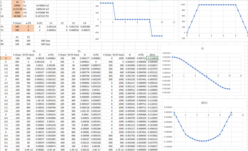
attached is a spreadsheet for the two point load case using my formula derivation above. FILE
Orange cells are user inputs
if you have an off balance load setup you can goal seek Theta in cell L20 to be 0 by changing cell A20 to get the location of maximum deflection.

For the example calcs below beam is a W40x149, ka = tw*d = 24.066 in^2 with two 500 kip point loads at 2ft and 8ft, L = 10 ft.
Screen clip from commercial software with shear deformation included showing exact agreement:
(nodes in screenshot are in 1ft increments)
Capture_ve6cte.png


Spreadsheet results (I use a different sign convention so my theta and delta are the opposite sign):
Capture_nvqhtb.png


My Personal Open Source Structural Applications:

Open Source Structural GitHub Group:
 
that's gotta be worth an LPS !

another day in paradise, or is paradise one day closer ?
 
If you need it to be metric adjust the inputs and the formulas in column D so the E thru kA values in column D match the units you want to use for length

Adjust the P1 and P2 force inputs to align with the units on E and G
Adjust the "a" value to match the length units

That gets all the inputs into consistent units

Deflection reported in column M is in the consistent length unit, adjust the multiplier in column N to get to the units you want.


My Personal Open Source Structural Applications:

Open Source Structural GitHub Group:
 
The suitability of Timoshenko beam equation is influenced by the geometric consideration and material properties. The codes do define what geometry conditions constitute a "deep beam" situation, then the Timoshenko's derivation included the material properties, E and G. It is safe to say that it is applicable to the majority of structural beams that behave in line with the general beam theories. However, Timoshenko did warn for beam with large deflection, that warrant another solution. But I don't know where is the line, for now.
 
Status
Not open for further replies.

Part and Inventory Search

Sponsor