Continue to Site

Eng-Tips is the largest engineering community on the Internet

Intelligent Work Forums for Engineering Professionals

  • Congratulations cowski on being selected by the Eng-Tips community for having the most helpful posts in the forums last week. Way to Go!

Finding the optimum slotted shape for this mechanism 2

Status
Not open for further replies.

eli28

Aerospace
Oct 20, 2019
109
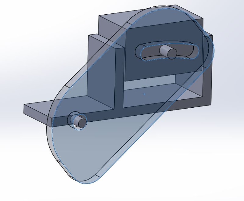
Does anyone has an idea how can I find the optimum shape of the slot in the mechanism described schematically in the attached picture?
I can say that we probably want the lower slot surface normals to coincide with the vertical axis of movement, but I am not sure how to analytically or technically plotting it (maybe in CAD?)
mechanism_n6yfql.jpg
 
Replies continue below

Recommended for you

Thanks...
Isn't there an option using the CAD (solidworks for example) for doing it?
 
Basing a slot off of CAD geometry seems like trying to have someone else optimize the problem without all of the parameters. What is the optimum solution - doesn't that depend upon your application? To me a slot design depends upon the loading, speeds involved, the cam follower type and capacity, potential for instantaneous reversal of the follower rotation, the allowable Hertz stress for the track, etc.
 
You have an opportunity to learn from our ancestors. You know, those guys who designed so many amazing inventions, won World War II, and landed man on the moon, all without the assistance of CAD. How did they do it? How did they design cams? They did it logically, step by step. Where do you want the slide to be when the arm is at its lowest position? Lay it out. Where do you want the slide to be in the arm's highest position? Start with one and make incremental layouts, maybe every 5 degrees of arm rotation. The result will be a path you can connect like connect-the-dots. Figure it out. You can do it. They weren't any smarter than you.
 
Hey Jboggs
That's what I did (incrementally), but I just wanted to make sure that there isn't more accurate and simple way.
And as for our ancestors, you are right... I am trying to have a deep understanding of everything I do, but reality wins and if you want to finish your work on time you can't stop and explore everything...maybe I am wrong, but that's the reason I don't stop every step.
what is your opinion about it? I guess you also need to accept compromises...
 
If the desired answer is a Solidworks pick and click then the Solidworks forum is the place to go.

The task as described is missing too many constraints to define "optimum". If low friction is the desire, then placing a cam follower roller bearing on the block would do that. If one wants to eliminate high contact pressure, replace the cam with another bar to build a 4-bar linkage.

Minimization is what calculus was invented for. It does has the defect that it requires understanding what the problem is.

 
Hey, I think I understand what I want to achieve.
I want that the force acting on the shaft in each position coincides with the movement direction (vertical) and hence preventing as much as possible horizontal forces, leading to higher friction, wear and low efficiency...
 
That's what you -want- which is not the same as understanding anything about it. I want my stocks to go up in price but that doesn't mean I understand all the market forces that might cause that to happen.
 
Then you want a simple horizontal slot. Therefore no horizontal forces on the pin as it slides, neglecting friction. 😐

Ted
 
you want the block to travel up and down, and the link to pivot about the fixed point.

I'm sure there's some tool in SW to do this (maybe check YT).

For olde school, position the block at several points along it's travel, see where the peg is, see where your contact points are.
I wonder if you want a "horizontal" arc as shown, or a "vertical" one ?

another day in paradise, or is paradise one day closer ?
 
Hey, thank you all for replying and contributing to the discussion.

3DDave - I think that neglecting friction isn't the right way in my case since the slot's shape design was originally meant to prevent high horizontal friction, wear and low efficiency...


rb1957 - your suggestion is good and that's what I finally did, but tried to find an easier, faster and more accurate way.

 
I did not say to neglect friction. I suggested eliminating it.
 
look into the dynamics/mechanics component of your s/ware … this sounds like something it should do for you these days (or else make the tool yourself, and make some money !?)

another day in paradise, or is paradise one day closer ?
 
thank you everyone for replying
 
Ive done a couple similar setups.

One thing these don't like is linear movement without rotation. Tends to bind. Not sure why, but it does.
 
The way that I would examine your problem is to draw lines between the center points of the pivot point and of the block pin at several positions of the block that is to be raised and lowered. Measure the lengths of these lines and proceed to draw the shape of the slot that will accommodate these various lengths.
Also, you will have horizontal forces because of the weight of the block that is being raised and lowered.
Also study the Geneva wheel as that could be a solution.
 
Status
Not open for further replies.

Part and Inventory Search

Sponsor