Continue to Site

Eng-Tips is the largest engineering community on the Internet

Intelligent Work Forums for Engineering Professionals

  • Congratulations waross on being selected by the Eng-Tips community for having the most helpful posts in the forums last week. Way to Go!

Finding Torque vs RPM without Torque sensor Three Phase Induction Motor 2

Status
Not open for further replies.

zaraf1

Automotive
Mar 18, 2018
8
Dear community,

For one of the projects which I am currently working on, I want to quantify my three phase AC induction motor in the following ways:

1. Find Torque vs RPM Curve
2.Find Efficiency vs RPM Curve

Now since I dont have the industrial "Torque Sensor" to plot Torque vs RPM curves, I thought I could proceed the following way. Luckily I have two same motors :) :

So I take the first motor and make it a drive. Then I take the second motor and make it function like a load. The two motors shall be coupled on the shaft. After that I want to rotate the drive motor uptil 100 RPM with load motor being idle. Slowly the load motor is powered up. In response the drive motor would also enhance it's power by drawing more current. Due to this the RPM shall stay constant all the time. At one point increasing load would start decreasing the rpm. Now shortly before this point the max power required to maintain the "constant rpm" will be calculated. This will be done using:
Power input = Mean of three phase currents x Voltage x PF

Using this value of the Power, torque for this particular RPM will be calculated using Power=TorquexRPM

The procedure will be repeated for increasing RPMs like 100, 200, 300 etc and then a plot of Torque vs RPM be plotted.

Now this will be an approximation because the mechanical output of motor is factored by efficiency which we dont have.

Do you think that this experiment is making sense?

Regards
Zaraf
 
Replies continue below

Recommended for you

You may have made some false assumptions.
Efficiency is constant: No, it is related to loading, applied voltage and frequency.
PF is constant: No, PF is related to motor loading, frequency and applied voltage.
The speed of an induction motor is constant: No, the speed drops as the load is applied.
Maximum torque is equal to rated torque: No, loading and running at maximum torque can be expected to result in motor burnout in less than one minute.
Maximum torque may be 250% of rated torque.
Efficiency is related to losses.
Some losses are affected by applied voltage.
Some losses are affected by current.
Some losses are affected by frequency.
Some losses are affected by slip frequency.
Some losses are affected by the motor temperature.
All losses are related to at least two and possibly more of these factors.
Running a motor on a variable drive at 200 RPM will not produce results anywhere near the results gained by loading a 1760 RPM rated motor down to 200 RPM.
Take a look at the Cowern Papers. This is a good introduction to motor characteristics.
Link
Look at the curves on .PDF page 7, .PDF page 10,

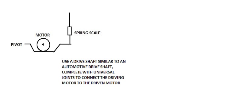
A torque sensor is easy to build.
Mount one of the motors on a pivoting base and measure the reaction torque with a spring scale.

Take your measurements quickly. An old rule of thumb is 14 seconds of locked rotor current to burn-out.


Bill
--------------------
"Why not the best?"
Jimmy Carter
 
Hello Waross,

Thanks for your valuable reply. I understand what you mean and also convinced that the experiment is based on lots of assumptions. As a background information, the application of the motor (15KW nominal and 30kW max) is in an electric car and we have a motor controller designed for it. Now I was thinking that probably we could lock our system to one particular RPM since the motor controller will regulate this by supplying more current even if the load is getting increased? Additionally you are right that the PF and the efficiency is not constant. But probably we could use the DC current and voltage to calculate the power drawn since our system is connected to Lead-Acid at the back? And use this power (which is very rough) to estimate the Torque we locked at that RPM? We also have datasheets from supplier which we can use as starting points and therefore will try to keep motor below maximum torque thus not burning the motor out.
The problem is that the torque sensors for this range are very expensive. If you think this wont work, probably we try making our own.

Do you still think that the experiment is flawed?

 
An easy dyno can be built from a braking drum and a belt with a tensioning screw and a force meter, usually a simple weigh scale that is arranged to measure actual braking force. Provide the drum with rims so that cooling water can be added inside it. Read force from the scale. Easy, simple, fairly accurate.

Gunnar Englund
--------------------------------------
Half full - Half empty? I don't mind. It's what in it that counts.
 
I suggest that rather than the maximum torque you would be better knowing the maximum safe time at a given torque.
Current will be more important than torque.
The first limit for continuous operation is heat or temperature. Motors are designed to run at a stated temperature rise.
Exceeding the manufacturer's rated current will overheat the motor and sooner or later burn out the windings.
Torque is related to current squared and with a variable frequency drive is fairly constant across the RPM range.
With most motor designs there is less cooling at slower speeds and the torque loading and current should be reduced accordingly.
But for a vehicle motor you may want to intentionally allow short time overloading.
You may consider embedding temperature sensors in the windings to reduce the current/torque when the internal temperature becomes dangerously high.
You may run the motor at rated speed and 100% load to determine the length of time for the temperature to stabilize.
Chart the temperature. The temperature will increase 63% of the total temperature rise in one time constant. For most work it is safe to assume that the final temperature will be reached in five time constants.
With a sensor reporting the internal temperature of the windings and knowing the time constant of the motor, your computer algorithm may determine the safe working time at a given overload condition.
Gunnar's suggestion has been tried and true for a century or so.
If you will be using a motor as a load, this sketch maybe interesting. (Don't forget that the load motor will also get hot.)
TORQUE_MEASURE_cgdlc7.jpg


Bill
--------------------
"Why not the best?"
Jimmy Carter
 
Nice summation Bill.

Question anybody:
If you're trying to measure the torque using, say, a strap-brake how does the roasting strap and heating drum affect the torque reading? Is it the "load"? If it is, how could you ever quantify it? (a bunch of heat radiating, convecting, and conducting down the shaft)

Keith Cress
kcress -
 
Hi Keith.
A lot like the brake drum on your (old) car. grin
Mechanical energy is converted into heat energy and the heat is radiated and conducted away.
If it is a large capacity it may be water cooled and boiling water absorbs a lot of BTUs.
With automobile drum brakes, the braking force is restrained by the anchor pin.
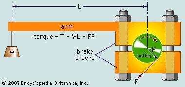
When measuring torque, the rotation of the shoes or band is restrained by an arm attached to a spring scale. The force on the scale times the length of the arm gives foot lbs. directly.
55220-004-F70AE81F_lo91ix.jpg

Note: Keith knows this. He asked the question to prod me into providing more details for the benefit of others who may not be familiar with the Prony brake. (Invented by Gaspard de Prony in 1821)
This shows an arrangement of a Prony brake. For 15 kW to 30 kW you need a larger diameter brake drum and probably water cooling as described by Gunnar.
By the way, whoever drew this sketch is not much in the real world.
You can expect the weight to sit on the ground as the brakes are applied, and then suddenly launch as the braking force exceeds the mass of the weights.
A spring scale will work so much better than weights.
Another note re: torque at different speeds:
Torque is roughly proportional to slip frequency.
With a variable frequency drive, the torque will be about the same at any speed.
Example: A motor is rated at 1760 RPM. The slip is 40 RPM. The slip frequency is (1-(40RPM/1800RPM) x 60Hz = 1.3 Hz.
For whatever speed the motor drive frequency is set to, at about 40 RPM less, a design B motor will develop full rated torque.
eg:
30 Hz = 900 RPM. Full load torque at 860 RPM. (900 RPM - 40 RPM)
15 Hz = 450 RPM. Full load torque at 410 RPM. (450 RPM - 40 RPM)
5 Hz = 150 RPM. Full load torque at 110 RPM. (150 RPM - 40 RPM)

Bill
--------------------
"Why not the best?"
Jimmy Carter
 
If the controller is decent then it should produce a fairly constant torque at all speeds within the constant V/Hz range of the motor.

You likely want the load setup to be bigger than the motor you're testing, enough that the load setup is never overloaded or only lightly overloaded. That way, you tell the device under test to output maximum torque and then allow the load to ramp the speed while you record the required data. If the load setup uses decent enough electronics then if should be able to calculate a reasonable torque value for you. You won't like the price for a proper load setup much better than the load cell price though.
 
Hello Guys,

I love your answers and so the concept of Prony Brakes. I am willing to invest in the drum brake and a spring balance as Skogsgurra mentioned above. But if I understood the concept from Waross correctly then this setup measures the static torque. That means under 0 RPM, since the spring balance will restrict any rotation. So how does this gives us "Torque vs RPM" curve?

I was thinking to us this Prony Dynamometer to calibrate one motor. So what I will plot is the Torque (as read from scale) vs. the Input DC current. And then use this curve to get to the torque of the running system by watching current values. But this wont work precisely too, since the torque is pretty constant?

Other idea would be to couple two Motors making one Drive and other Load as said before, and then tying the Prony Dynamometer on the shaft coupler. But even in this case we wont get any RPM due to spring balance.

@Waross: Thanks for the measuring torque safely advice: the motor has an encoder and a temperature sensor, and the Motor Controller can cut-off if the Temperature gets critical.
 
zaraf,

The brake is not actuated to full lock, i.e. the brake is slipping so that the motor continues to rotate, preferrably at a constant speed. The dynamic torque generated is measured by the reaction forces on the brake.
 
The motor tends to turn the braking arrangement. The brake is slipping and thus generating heat, that's why you may need to use water cooling.
When you apply the drum brakes in a car, the brake shoes tend to turn with the wheel, but are restrained by the anchor. In the Prony brake the turning effort is restrained by the spring balance and so may be measured.
By setting the brake so tight that the brake will not slip and the motor will not turn, you can measure the starting torque.
Remember that the maximum available torque of a motor may be 200% or more of the safe continuous torque.

Bill
--------------------
"Why not the best?"
Jimmy Carter
 
Hello Waross and other members,

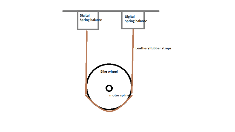
After getting inspired by your thoughts, I have decided to go for the following arrangement to measure my motor torque.
Unbenannt_xpzwo9.png


My questions are:

1. Do you think this would work for a torque of 120Nm
2. Our motor has a max power of 30KW, now I was thinking that the output power has to get dissipated in form of friction (heat, sound etc.). Do you think the setup can handle this for such a high power.
3. Probably I will try to add an external cooling on the Rim if required.

Your thoughts please.
 
30kW of braking through a bike wheel and a leather strap......not going to happen.

Use another motor as the brake. Mount it with the shaft going through pillow blocks so you can attach a lever to a scale.
 
Lionel said:
Mount it with the shaft going through pillow blocks so you can attach a lever to a scale.
I like that Lionel.


Bill
--------------------
"Why not the best?"
Jimmy Carter
 
Status
Not open for further replies.

Part and Inventory Search

Sponsor