Continue to Site

Eng-Tips is the largest engineering community on the Internet

Intelligent Work Forums for Engineering Professionals

  • Congratulations KootK on being selected by the Eng-Tips community for having the most helpful posts in the forums last week. Way to Go!

Finned Tube Heat Exchanger 2

Status
Not open for further replies.

VFreshEngineer

Mechanical
Jan 7, 2022
14
Hello everyone, hope You all are staying safe in these challenging times.

I'm designing fin-tube heat exchanger (water-air). I have all the calculations needed, heat exchanger is manufactured & tested and works great, but as a curious person I'm still wondering about some theoretical aspects. I currently don't have any collegues in mechanical department, so I really appreciate any discussion on the subject. I'm still very fresh engineer, so correct me if I'm wrong anywhere along the way.

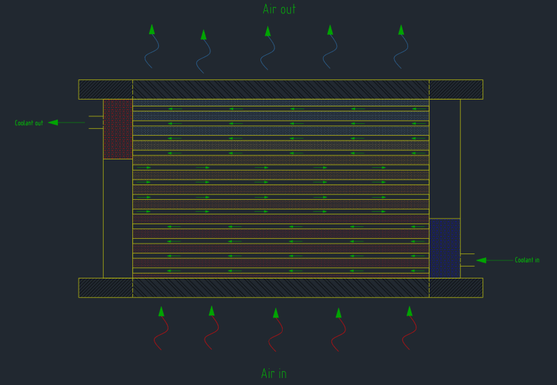
To visualize the case a little better, here is a simplified drawing of heat exchanger:
Cooler_kap13o.png


Knowing the coolant flow for the cooling loop and the size of the Inlet/Outlet coolant connections, we can find the velocity of fluid using: Q = V/t = A*v = (πd[sup]2[/sup]v)/4
If coolant connections sizes are the same, in&out velocity of fluid will also be the same. (Flow in = Flow out = constant)

Questions:
1. What about the velocity of fluid inside the tubes? Will the flow inside single fin-tube be "Q/number of tubes"? (Q: system flow)
2. If (1) is the correct assumption, then more fin tubes inside heat exchanger = lower fluid velocity inside single fin-tube = larger cooling capacity, but higher outlet temperature of the coolant.
3. I'm calculating Reynolds Number by multiplying "Mass Flow unit Area" with fin-tube diameter and dividing the product with "Dynamic Exhaust Viscosity @ Mean Temperature". [Re=(G[sub]n[/sub]*d)/μ[sub]E_Mean[/sub]]. My superior says that Reynolds number should be below 12000, but he doesn't really know how to support this statement with scientific knowledge. Is there any way to establish the limits for Reynolds number? Or is there some kind of rule of thumb? I've only learned that for a flow inside a pipe to be laminar, the Reynolds number should be kept under 2000, but that's simplification I remember from uni.
4. Is there any critical velocity for the fluid flow? I remember I've read somewhere that it's usually kept under 3 m/s, as a rule of thumb. However, I don't know more. The only reason I can think of is that the force of moving fluid on the structure (walls) shouldn't exceed certain value.

Anyway, I think that's it for now. If any additional questions will pop in my head, I'll surely update.
I appreciate every single input. Thanks in advance!
 
Replies continue below

Recommended for you

Are the tubes all plumbed in parallel, series, of a combination?
High velocity promotes mixing and speeds heat transfer.
But high V also increases pressure drop (pumping losses) and can promote erosion in susceptible materials (usually softer ones like Cu or Al).

= = = = = = = = = = = = = = = = = = = =
P.E. Metallurgy, consulting work welcomed
 
Hi Ed and thanks for the answer.

Tubes are in parallel.
Is there any way to determine critical in/out velocity?
What about the statements (1) and (2) I made above? Can You either confirm or deny?
 
You know the total flow and the total ID area of the tubes so you can figure out the average velocity.
Unless the total ID area of the tubes is less than your inlet you will have significant variation in flow from one tube to the next.

While the flow velocity does impact heat transfer there isn't a step function in the range of 1.5 m/s - 4 m/s, it is fairly proportional.
Some materials can tolerate 30 m/s (most SS), others begin to have erosion issues above 2 m/s (Cu).

= = = = = = = = = = = = = = = = = = = =
P.E. Metallurgy, consulting work welcomed
 
The fact that the inlet and outlet are offset from each other would contribute to the flow being evenly distributed between the fins. If the inlet and outlet were directly opposite each other then you would be more likely to have more flow through one side of the heat exchanger than the other.

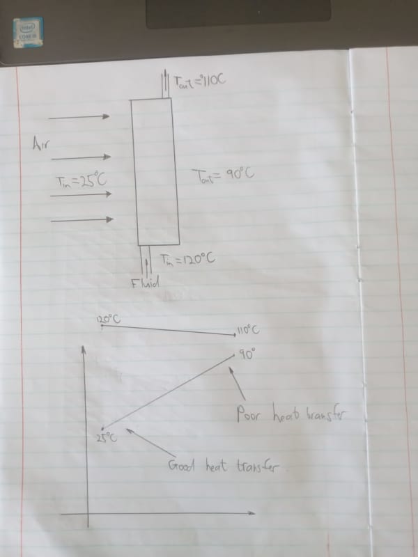
Then you said something interesting that is a common misconception with heat exchangers. You said something about lower velocity causing improved heat transfer because the inlet and outlet temperature are more different. This is not an indication of heat transfer efficiency. If your outlet temperature is much lower or higher than your inlet temperature it could actually be an indication of poor heat transfer. It means that the delta T between the heating fluid and cooling fluid closer to outlet is becoming less and less and that means that heat transfer is becoming worse the closer your getting to the outlet. It means that the flowrate of the fluid that you are heating or cooling is too low.

HeatExchanger_ddueme.jpg


This is a good example of where an increase of the air flowrate would improve the heat transfer. If you increase the air flowrate to a point where the outlet air temperature is about 40 degrees celsius you would improve the overall heat transfer by a lot. You could probably drop your inlet temperature of the fluid into the heat exchanger and by extension the overall system temperature of whatever you are cooling. Obviously this is not always a good thing, but it is food for though nevertheless.
 
Hi,
A great resource about heat exchanger available using your favorite search engine is Wolverine engineering data book 2

Good luck
Pierre
 
As mentioned, turbulent flow is used in heat exchangers to promote heat transfer. The standard flow profile of laminar flow (which I assume you're familiar with if you remember the Re for transition is ~2000) has low velocity at the wall, which can lead to the fluid building an "insulative layer" on the wall of the tube and not transferring temperature to the entire column of flow in the tube.

1. What about the velocity of fluid inside the tubes? Will the flow inside single fin-tube be "Q/number of tubes"? (Q: system flow)
- yes, assume you're equally distributing the flow to make the math easier. In reality there will be slight discrepancies between individual tubes, as long as you're not designing a setup that will starve flow from certain tubes any small differences will come out in the average.

2. If (1) is the correct assumption, then more fin tubes inside heat exchanger = lower fluid velocity inside single fin-tube = larger cooling capacity, but higher outlet temperature of the coolant.
-more finned tubes yields more surface area for heat transfer and will result in a change in pressure drop, both for the fluid passing through the tubes and the air passing over them. You need to balance heat transfer performance with system performance, ensuring that the required pressure drop remains within the bounds of the design. Packing more tubes in means you need to be checking air pressure drop and face velocity for the air to ensure you're not choking the fans off.

This is referred to as "circuiting" in air-cooled heat exchanger design/specification. Coil manufacturers have a tubesheet that gets populated with finned tubes, and a series of hairpins are brazed on the ends of the tubes to make the interconnections. The patterning of these hairpin tubes determines the flow pattern of the coil, how many passes are made by the fluid, how many parallel tubes are being used, etc. The circuiting is tuned to balance pressure drop and thermal performance for a particular unit, and the total number of tubes in the coil regardless of circuiting determines fan performance.

Tube diameter can also be changed in the design to optimize performance. Smaller tubes require more pressure, but yield more surface area per volume, and can remain turbulent at lower flow/velocity. Typically a manufacturer will not change tube diameter for a certain product and will do most of the performance changes with circuiting certain sized coils of a specific design, and scale that coil design bigger/smaller to create a range of product.

3. I'm calculating Reynolds Number by multiplying "Mass Flow unit Area" with fin-tube diameter and dividing the product with "Dynamic Exhaust Viscosity @ Mean Temperature". [Re=(Gn*d)/μE_Mean]. My superior says that Reynolds number should be below 12000, but he doesn't really know how to support this statement with scientific knowledge. Is there any way to establish the limits for Reynolds number? Or is there some kind of rule of thumb? I've only learned that for a flow inside a pipe to be laminar, the Reynolds number should be kept under 2000, but that's simplification I remember from uni.
-Keep Re above 2000 inside heat exchangers, and below 2000 in normal flowing pipes.

4. Is there any critical velocity for the fluid flow? I remember I've read somewhere that it's usually kept under 3 m/s, as a rule of thumb. However, I don't know more. The only reason I can think of is that the force of moving fluid on the structure (walls) shouldn't exceed certain value.
-There are critical velocities, but as mentioned it's more of a function of material properties. Plus any contamination in your process fluid can contribute to erosion from flow.


That said, this barely scratches the surface in air-cooled heat exchanger design. As Joe591 mentioned there is a lot of design work that goes further into optimization for approach temperature, efficiency, fan designs, serviceability, controls, etc.
 
Pierre, Walt - Thank You for the book, I've started to read it to get a better understanding of concepts within heat transfer. Great read so far!

Rputvin - Thank You for your throughout answer with explainations. I really appreciate it.
 
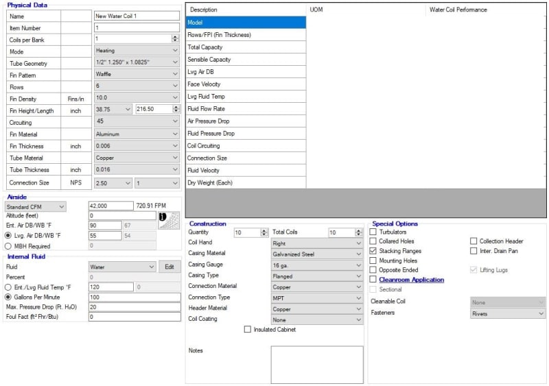
Vfresh, just to give you a little more to chew on - this is a section of the input screen for a coil selection software. It gives you an idea of some of the design variables that influence performance. If you can get your hands on selection software and a crash course in using it they can be somewhat illuminating to mess around with and try and understand why different input changes influence the performance (and you don't need to do the math yourself every time)

If you go deeper down the rabbit hole on these units be aware that everyone uses a lot of different terminology. For instance the coil snip is in "heating" even though the project is working to cool a process because of how this company arranges the terminology for their product, and the item is a "water coil" despite being rated and used for a wide array of fluids. Inlet/outlet, entering/leaving, heating/cooling, supply/return, etc can all flip depending on the framing of the conversation. The same product is called something different, sometimes incorrectly, by every customer, vendor, and colleague; Dry Cooler, Radiator, Fin-Fan Unit, Fluid Cooler, "Chiller", Air Cooled Heat Exchanger, Heat Exchanger, Water Coil, Aerial Cooler, I'm probably forgetting 10 more I've heard.

Coil_Parameters_z5wtxd.jpg
 
@Strong
That link was a waste of time; the download only contains the ToC and cover page, a total of 7 pages.

It appears to be something that requires payment from a legitimate vendor like
TTFN (ta ta for now)
I can do absolutely anything. I'm an expert! faq731-376 forum1529 Entire Forum list
 
Status
Not open for further replies.

Part and Inventory Search

Sponsor