Continue to Site

Eng-Tips is the largest engineering community on the Internet

Intelligent Work Forums for Engineering Professionals

  • Congratulations waross on being selected by the Eng-Tips community for having the most helpful posts in the forums last week. Way to Go!

Fitting shear studs on short spans 1

Status
Not open for further replies.

Dusni

Structural
Aug 7, 2016
10
Hi,

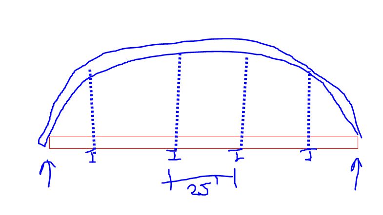
I'm working on a tied arch. The deck is supported by continuous stringers. The stringers are supported by floor beams spaced @ 25'. The floor beams are supported by hanger rods attached to the arch ribs.

AASHTO requires (2) checks for shear studs:
Fatigue: Use VQ/It to calc shear flow due to fatigue load and compare to stud capacity. No problem here.
Strength: Shear load = min of deck strength and Fy * Ag of the beam. Then No. of studs between point of max +M and adjacent 0 moment = shear load/stud capacity (for continuous spans there's a similar provision). I end up with a crazy number of studs (3 per row, rows @ 4"). I could see if it was just 1 or 2 spans, but considering the deck and beams are continuous over many spans it seems like studs throughout the bridge would work together in locking the beam and slab together. In other words 5 spans @ 20' would require wayy more studs than 2 spans @ 50' although both are 100' total. I suppose in a +M region the deck is in compression and the studs are pushed in one direction and in the adjacent -M regions the deck is in tension and the studs are pushed in the opposite direction so in that sense the studs are not all working together? Am I making any sense?

Thanks
 
Replies continue below

Recommended for you

I, personally, would avoid shear studs...

Rather than think climate change and the corona virus as science, think of it as the wrath of God. Feel any better?

-Dik
 
You need to provide a drawing. Your verbal description is insufficient.

BA
 
My money's on a setup like that shown below.

OP said:
I suppose in a +M region the deck is in compression and the studs are pushed in one direction and in the adjacent -M regions the deck is in tension and the studs are pushed in the opposite direction so in that sense the studs are not all working together?

That right there would be your answer I think. We treat the distribution of studs pseudo plastically but, certainly, they need to respect sign changes in the shear being transferred.

The stringers are your arch tie, correct? If so, it might be worth giving some consideration to how that direct tension in your beams will affect the composite flexural behavior.

C01_tkxrcb.jpg
 
Kootk, that drawing is basically it. There are separate arch ties though and the floor beams frame into the ties. There is tension transferred to the deck and stringers, since they are indirectly attached to a giant tension member but thats another can of worms.

So I kind of answered my question in my original post... It just still seems weird that if you take 5 spans at 20' you end up with about 5x more studs then 1 span @ 100'. At some point you end up with so many studs it seems excessive to prevent the deck from slipping. Even if one region causes deck compression and the adjacent region tension it seems like you're conservatively ignoring some effect of the deck being continuous.
 
OP said:
t just still seems weird that if you take 5 spans at 20' you end up with about 5x more studs then 1 span @ 100'.

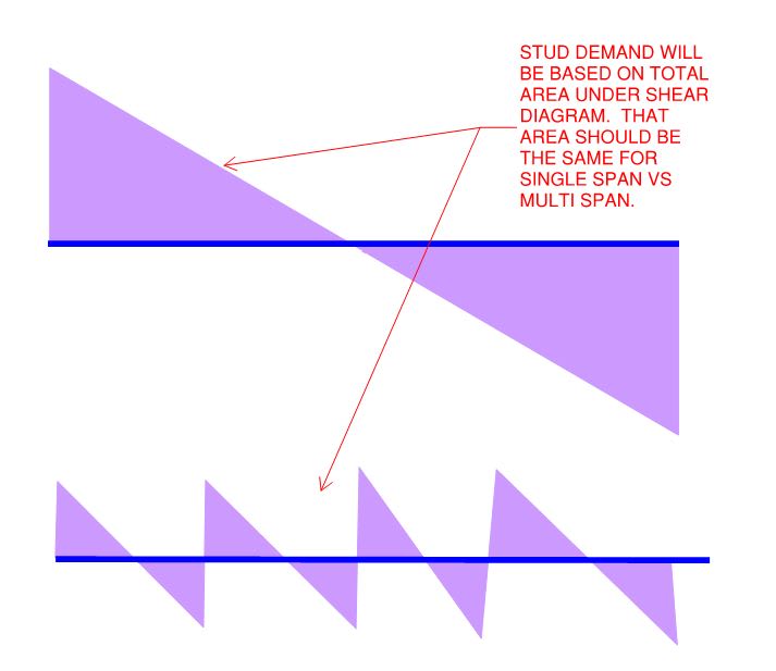
I get your intuition on this. However, I'm not sure that intuition is accurate. Would it not break down like this?

C01_uixmbd.jpg
 
I agree with your diagram in theory, but per AASHTO the No. of Studs = total shear load / stud capacity, where shear load is smaller of:
1) 0.85*f'c*b*ts
2) fy * Ag

So its not based directly on loading, but rather the force required to develop the strength of the slab or yielding in the full cross-section of the beam. So for a short span you have the same design load but a shorter length to fit studs.
 
Right, I see what you mean. If the studs are designed to fully develop the axial capacity of both materials, that changes things some.

I still think that the logic of my graphs applies though, albeit viewed from a different angle. For the same length, the single span beam will will be MUCH larger than the five span beam right? Ergo [fy * Ag] will also be much larger for the single span beam and, again, the quantity of shear studs required for both cases should work out to be roughly the same. Of course, this assumes that the beams are sized for flexure and sized efficiently. If something other than flexure is driving the beam size choices, that messes with the logic. And, in that case, one might make a rational argument for modifying the [fy * Ag] requirement.
 
I've ended up with shear studs as close as 9" row spacing (3 studs per row), but it was to meet the fatigue stress requirements. Are the stringers really compact and heavy? What size studs are you using?

Rod Smith, P.E., The artist formerly known as HotRod10
 
Dusni said:
So I kind of answered my question in my original post... It just still seems weird that if you take 5 spans at 20' you end up with about 5x more studs then 1 span @ 100'. At some point you end up with so many studs it seems excessive to prevent the deck from slipping. Even if one region causes deck compression and the adjacent region tension it seems like you're conservatively ignoring some effect of the deck being continuous.

That statement cannot be true. One span at 100' should require 5 times the number of studs as 5 spans @ 20'.

KootK said:
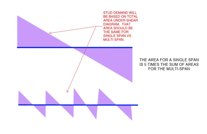
I get your intuition on this. However, I'm not sure that intuition is accurate. Would it not break down like this?
image_yfndnm.png


I don't think so. The area of the V diagram for the 100' span is 25 times that of a single 20' span, or 5 times the sum of all 20' spans. That is because Vmax and L for the 100' span are each 5 times that of a 20' span, so their product is 25 times that of a 20' span.


BA
 
For the Strength limit states, AASHTO requires enough studs to transfer the total force of the entire steel girder in tension or the entire concrete effective flange in compression between every point of maximum positive moment (at midspan) and maximum negative moment (at supports).

The calculated shear due to fatigue loading is used to calculate the spacing of studs at any and all points along the girder based on the fatigue stress limit of the studs; this is typically made more complicated by the increase in the number of calculated stress cycles (and therefore a lower stress threshold) near the supports.

Btw, that shear diagram with the nice triangular areas, is only accurate for uniform dead loads. The shear diagram for total load, including moving live loads, is alot uglier. The sum of max shear on a 100' span is also not even close to the sum of the shears on the 5 spans of 20'. Of course, the aforementioned AASHTO requirements make it a moot point, anyway.

Making the superstructure in question composite is probably not economical, unless the depth available for the superstructure is severely limited and limiting deflections is required.

Rod Smith, P.E., The artist formerly known as HotRod10
 
BridgeSmith said:
Btw, that shear diagram with the nice triangular areas, is only accurate for uniform dead loads. The shear diagram for total load, including moving live loads, is alot uglier.

I recognize that and was merely trying to make my point as simply and efficiently as possible. Doing it with moving loads would have been an explaining nightmare.

Bridgesmith said:
The sum of max shear on a 100' span is also not even close to the sum of the shears on the 5 spans of 20'.

With respect to any shear flow based stud demand, it's not the maximum shears that should be added. Rather, it's the areas under the shear diagrams that should be summed.
 
KootK said:
With respect to any shear flow based stud demand, it's not the maximum shears that should be added. Rather, it's the areas under the shear diagrams that should be summed.

I can't really wrap my brain around that, to say whether I agree or not. As I said, for shear studs on bridges, the only relevant shear demand is the fatigue shear range at any given point, which determines the stud spacing at that point, based on the VQ/I at the top of the top flange.

Rod Smith, P.E., The artist formerly known as HotRod10
 
The area under the shear diagram is the moment at midspan.

BA
 
BAretired said:
The area under the shear diagram is the moment at midspan.

I think we all know that much, although technically, the moment at any point is the accumulated area under shear curve. It's not necessarily at max at midspan, unless the shear happens to go to zero at that point.

Rod Smith, P.E., The artist formerly known as HotRod10
 
Status
Not open for further replies.

Part and Inventory Search

Sponsor