Continue to Site

Eng-Tips is the largest engineering community on the Internet

Intelligent Work Forums for Engineering Professionals

  • Congratulations KootK on being selected by the Eng-Tips community for having the most helpful posts in the forums last week. Way to Go!

Fix rotation parts at the axis instead of edge? 1

Status
Not open for further replies.

nxprouser

Mechanical
Feb 18, 2015
10
Hi to all, the stress results of my calculcations of rotation parts are always not as exact as it should be, because I have to make a fixed definition on an edge of the part, most of the time the edge of the most inner diameter.
I have heard that there is a possibility to fix a rotation part on its rotation axis. Does anybody know how to do it?
Regards
Sonja Schneider
 
Replies continue below

Recommended for you

Not sure what the mechanism is, but here is a way to model fixed or free rotation/translation: (whichever you need)

[ol 1]
[li]Connect all edge most diameter nodes to an RBE2 element (spider RBE2). The dependent (single set) node of your RBE2 should be at the center of that hole.[/li]
[li]At this dependent node, create a "coincident" node CBUSH element. One of the nodes of your CBUSH element will be this dependent node of your RBE2 element.[/li]
[li]Connect your 2nd node of the CBUSH element to the interface PART/ELEMENT. (Let's say if one of your parts is a tube modeled with shell elements, and the other part is a shell mesh part with a lug hole in it - where the tube will pass through- then you will have 2 separate RBE2 elements. One of them will be for the tube, the other one will be for the part with the lug hole. The 2 RBE2 elements' center (dependent) nodes will be coincident at the rotation axis. And your 1st CBUSH element node will be connected to one of these RBE2 center nodes; and your 2nd CBUSH element node will be connected to the other RBE2 center node)[/li]
[li]After you have 2 nodes of your CBUSH connected to the different interface parts, you can define the CBUSH stiffnesses (K1, K2, K3, K4, K5, K6 in the Nastran CBUSH Card) per your needs. (Let's say if you have free rotation on Z-axis, you can define a K6 value of 1 or 10. But if you have fixed rotation on Z-axis, then you can defined a K6 value of 1E10 or 10^10).[/li]
[li]Depending on the orientation of your CBUSH element, you can either define a separate coordinate system for your CBUSH, or if your rotational/translational axes are perfectly aligned with your Global Coordinate System, you might as well just use the Global Coordinate System to assign your K1, K2, K3, K4, K5, K6 stiffness values).[/li]
[/ol]

Just as a warning, "not assigning a K value in any rotational degree of freedom sometimes may lead to diagonal matrix errors due to singularities, so I would first suggest using dummy K values like 1 or 10 for free rotational DOFs.

Spaceship!!


Aerospace Engineer, M.Sc. / Aircraft Stress Engineer with 7 years of experience
(United States)
 
That sounds if it could work, I will try it tomorrow. Thank you very much for your extensively answer.
 
You're very welcome. Let me know if it is not resolved.

Spaceship!!


Aerospace Engineer, M.Sc. / Aircraft Stress Engineer with 7 years of experience
(United States)
 
I personally suggest you use an RBE3.

You can try to explore the 'UM' option while defining the RBE3, this way you can fix the 'dependent' node of the RBE3, and then chose to constrain 'sensible' independent nodes of the RBE3 along theta of a custom cylindrical coordinate system. You might want to update the nodal def. and o/p CSYS to this cyl. CSYS.

This technique is common when trying to simulate free expansion of a cylinder for example, while at the same time avoiding rigid body motion. Hope this helps.

Aerospace Stress Analysis and FEA Courses
Stressing Stresslessly!
 
Hello!,
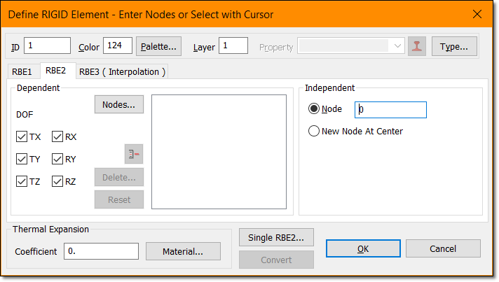
@aerostress82: I suppose is an slip, but the single point at the center of the spider RBE2 element is the INDEPENDENT node, not the dependent one. When using an RBE2, you need to specify a single independent grid point (the GN field) in which all six components are assigned as independent.

rbe2-independent-node_n4gjea.png


Best regards,
Blas.

~~~~~~~~~~~~~~~~~~~~~~
Blas Molero Hidalgo
Ingeniero Industrial
Director

IBERISA
48004 BILBAO (SPAIN)
WEB: Blog de FEMAP & NX Nastran:
 
Hi to all, thank you for your answers. I have now three RBE3-Elements one from first centerpoint to second centerpoint, next one from first centerpoint to first circle-edge, the third from second centerpoint to second circle-edge. (attached is a screenshot from an example).
I have set two fixed constraints to both centerpoints. The centrifugal load is for example 14000 rev/min.
When I start solving it finishes fastly and I have no result. The model setup check was ok. I have set the parameter AutoMPC=on.
I think that the RBE3-Elements are not really joined to my 3D-mesh, can it be?
 
 http://files.engineering.com/getfile.aspx?folder=604f6b1e-a3bd-43bc-a335-3ba9fe5dc68d&file=RBE3.jpg
Status
Not open for further replies.

Part and Inventory Search

Sponsor