Eng-Tips is the largest engineering community on the Internet

Intelligent Work Forums for Engineering Professionals

  • Congratulations waross on being selected by the Tek-Tips community for having the most helpful posts in the forums last week. Way to Go!

flair-bevel weld callout

Status
Not open for further replies.

paintballJim

Mechanical
Dec 23, 2009
56
0
0
US
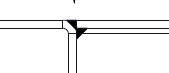
I am interested in the correct weld symbol for a flair-bevel weld where the weld is expected to be flush with the material when finished.
Capture1_a8vfic.png


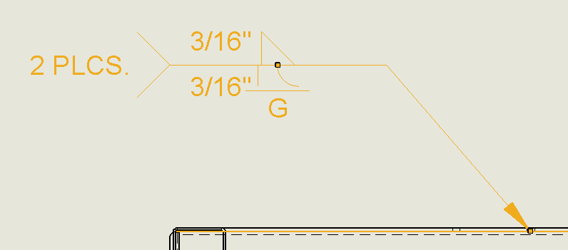
The question that has come up is if the throat dimension is needed if you indicate that the weld finish is flush. I have always added the weld size to my symbols but maybe that is not needed in this case? below I have added the dimension and a grind symbol, but if it is not necessary for the surface to be ground smooth is it acceptable to leave the dimension off and just expect the weld to be roughly flush to the material surface?
Capture_ckipur.png
 
Replies continue below

Recommended for you

If you are working as a chemist, you would have a chemical handbook. If you are designing steel structures, you would have a copy of the AISC Steel Construction Manual, if you were a mechanic you would have a toolbox with various wrenched and screw drivers, and a ratchet set.

If one wants to specify weld correctly they need to have an up to date edition of AWS A2.4.

If you can't afford the tools, don't take the job.

If you refer to AWS D1.1, Table 2.1 lists the maximum weld size based on the radius of the round component and the welding process. For your purposes you can use (5/16)R based on the bevel being filled flush. The welding symbol, by convention, is to list the radius followed by the weld size enclosed within brackets. Example: 1 (5/16) where 1 is the radius and 5/16 is the weld size.

Best regards - Al
 
The weld is to specify the radius or the material followed by the size of the weld? What happens if/when the shop forms a part with a larger radius than the weld is calling for? Is the part rejected? This is the first time I have ever heard of the weld calling out the radius of the material it is located on. Also, I have worked with over 60 engineers at 4 different companies, all metal fabrication businesses, and at only one location did even the company have a D1.1 book and that was purchased specifically because we had a government contract where we had to provide prints meeting D1.1 standards. When an organization is so proud of their standards that they make them cost prohibitive to own it is not surprising when most people don't know the standards.

With all that said, This doesn't answer the question as to whether or not the weld size designation is necessary or if the surface finish designation is sufficient in a symbol. I have seen books that seem to indicate both cases.
 
Terminology, terminology, terminology.

As you pointed out, the detail being welded is a flare bevel. The welding symbol standard most often referenced in the US is AWS A2.4. As I noted in my response, the convention is to define the radius of the round edge followed by the weld size. There is no throat dimension associated with the flare bevel unless one is looking at a text or standard that is out of date by twenty years or more.

I referenced AWS D1.1 because it is one of the few welding standards that provides a rational approach to determining the size of the flare bevel and flare V-groove. Most codes simply side step the issue.

The AWS Structural Welding Code/Steel does have provisions whereby a contractor can demonstrate larger weld sizes can be deposited via mockups. Designers often time mistakenly assume the weld is fused to the point of tangency where the round surface contacts the flat surface of the bevel groove or the two round surfaces make contact (or come as close as practical). Experience indicates that isn't the case when a typical arc welding process is used.

The attached sketch is one that I included in a WPS involving a double flare bevel groove weld. Notice the weld does not penetrate and fuse to the point of tangency.

Best regards - Al
 
 http://files.engineering.com/getfile.aspx?folder=d40292c0-53c1-4dbc-ba29-7d0183db815f&file=Flare_Bevel_-_Coupling_1-April-2010_Model_(1).jpg
In Canada we differentiate between the op sketch and GTAW's sketch. Both show E in the symbol, unless the radius of GTAW's sketch is <= 10mm, then it is shown with leg length and considered a flare bevel fillet weld.

CSAW59 - 2013
 
In the US they are simply flare groove welds, either a flare bevel groove weld or a flare V-groove weld.

As the sketch indicates, fusion to the root is not going to happen. that differentiates a fillet weld from a groove weld. Most designs assume the fillet weld is fused to the root. This assumption is needed in order to determine the dimension of the throat. If there is no fusion to the root, our strength calculations fall apart.

Best regards - Al
 
We use the intersection of the planar surface and a tangent to the curve of the flare that is perpendicular to the planar surface for fillet weld root(<=10mm). If the radius is >=10mm the face width of the weld shall also be shown along with E in the symbol. Width is x times the required effective throat where x is a factor based on process.
 
Terminology - I thought the (E) was the effective throat, which may or may not be related to an adjacent radius to be welded? When necessary, a sketch of the weld can be helpful to the welder if you aren't sure of the symbol. Especially if you will be grinding the weld afterwards.

Side note: how do you field inspect an (E) weld for specified penetration??


At one time, many years ago, the term throat was used to define the shortest distance from the weld root to the face and it was the "size" or joint penetration of a groove weld. However, terminology changes over time and now throat is use exclusively with the fillet weld. That change occurred about twenty years ago.

AWS D1.1 has prequalified joint details that have been used for many years because they provide adequate access for the welder to deposit a sound weld if they have the skills necessary to pass the prescribed welder qualification tests. The details are conservative enough, that if one follows the rules good welds can be made.

AWS D1.1/D1.1M:2015 includes table 2.1 that provides the user with a means of determining the weld size of both flare bevel and flare V-groove as a function of the radius of the round edge and welding process. Like many of the details included in D1.1, the details tend to be on the conservative side, so most welders have no problem depositing welds with the required size.

If one needs to verify the joint penetration/weld size, it can be done using UT with a straight beam transducer. One may have to grind the surface of the weld smooth to provide a flat surface for the UT transducer.

Best regards - Al
 
Al, You are correct, I should have said leg rather than throat. And I just checked the text I have (I am the only one here with any welding texts) and it is very close to the 20 years you mentioned. I try to use it because it is newer than my Blodgett books no matter how much good information they have. Guess I will have to make another purchase.
However you now have me concerned, if there is little or no root penetration expected from a flair bevel does it do much more than look good? You mentioned the fillet weld expects better penetration but my understanding has been that the material geometry dictates the weld and the geometry here would call for the flair bevel. Would it be acceptable then to place a fillet weld in this location and specify a flat surface rather than a leg dimension? Guess I am going to have to investigate the cost of A2.4 I just know that when the company purchased the D1.1 it was far out of what I could afford.
 
Of course I'm not sure how much good having the correct weld symbols will do me beyond making me feel better about my drawings. The owner of the company got after me for expecting the shop guys to know what side of a part the standard 3 projected views come from.
 
I talked to the NASSCO welder down the street. As gtaw notes, we rely on the prequalifications for good welds. He said occasionally they would grind a slot through the weld, dress it with a file, and look for voids with a USB colonoscope hooked up to a cell phone. He said that was rare, though.
Yes, I am 20 years out of date.
 
The strength of the weld is dependent on the shortest failure path through the weld, all else being equal.

Fillet welds, when they fail, do so in shear. If both legs are of equal length, the failure will be along a plane 22 1/2 degrees off the leg, not through the throat. However, we use the throat dimension, i.e., the shortest failure path, for the purposes of calculating the strength of the weld. The design approach works if there is fusion to the root and one can determine or assume the throat dimension. If unequal weld legs are specified, one can still use the shortest failure path, usually the shorter leg dimension to determine the strength of the weld. One must check to verify the base metal isn't over loaded, so AISC uses the allowable stress of 0.4 times the YS of the base metal in shear and 0.6 times the YS of the base metal for the allowable tensile stress.

The strength of the PJP and bevel grooves can be determined if the joint penetration (weld size) is known. When a prequalified groove detail is selected, the joint penetration is assumed to be some minimum dimension based on the depth of bevel and groove angle. If the groove angle is less than 60 degrees, one assumes the joint penetration is 1/8 inch less than the bevel depth. A conservative approach, but it hold true for a large percentage of welder.

Best regards - Al
 
Status
Not open for further replies.
Back
Top