Continue to Site

Eng-Tips is the largest engineering community on the Internet

Intelligent Work Forums for Engineering Professionals

  • Congratulations waross on being selected by the Eng-Tips community for having the most helpful posts in the forums last week. Way to Go!

Flange bolt loads with wear insert / orifice plate

Status
Not open for further replies.

HJL123

Mechanical
Jul 13, 2015
2
Hi,

I was just wanting to have a quick discussion regarding clamping of either a flange wear insert or orifice plate in between two flanges and the effect of this on bolt loads due to there being 2 gaskets and a steel plate in between rather that just a single gasket. Following from that too, a butterfly valve that is clamped in between (hence the wear insert) which makes that 3 gaskets that are being clamped (see drawing) on a set of bolts.

Does this change the gasket factor (m) or Design seating stress (y) from ASME VIII Div 1, appendix 2? What I was thinking is that the bolts will be doing up over a longer distance but the resistant still should be the same hence if all the gaskets are the same then m & y should be too. That is unless you assume the wear insert is another gasket material rather than ignoring it.

Cheers
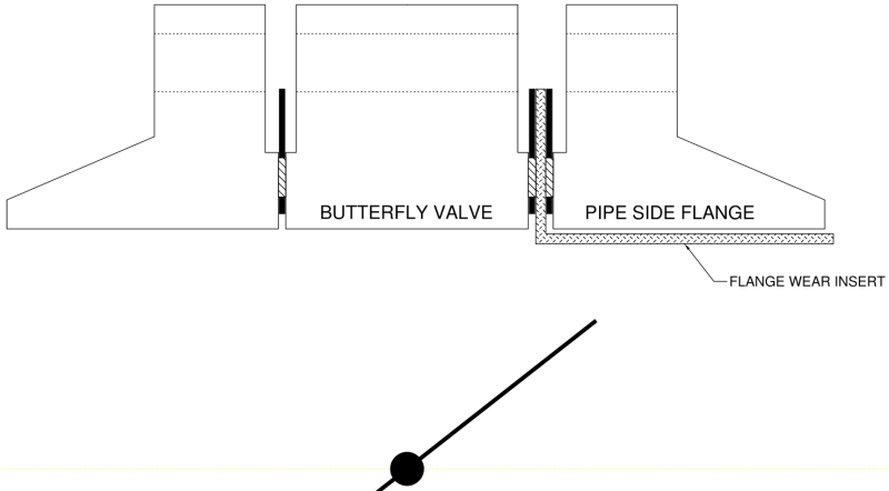

wear_insert_haby7y.png
 
Replies continue below

Recommended for you

I dont think its an issue. As you have the gaskets in series, the equivalent stiffness rate may slightly decrease.
I should keep the bolt loads the same, but if any different, only just slightly lower.
 
haydenjlewis,
Please explain the need, value and source of "a flange wear insert"


Sometimes its possible to do all the right things and still get bad results
 
I have seen this type of configuration before: in a set of failure analyses. If there is any chance that this location will see cycling of either pressure or temperature, then I would strongly suggest that you find another way, or involve an expert in bolted flange joints. Initial bolt load selection, along with gasket selection, will be critical to the long-term performance (the fairer investigation that I lead had a mean time between failures of six months...) Of the joint.

Gaskets in parallel result in stiffness equal to the inverse of the sum of the inverses of the single gasket stiffness (1/Y1 + 1/Y2 + ...)^-1.

As a bare minimum, I would suggest something other than a spiral-wound gasket; they tend to fail rather catastrophically when bolt load is lost.
 
Thanks everyone,

XL83NL, thanks for your comments, along the same thoughts of mine.

Pennpiper, the wear insert is to protect the flange against erosion caused by the fluid passing through the butterfly valve when it is not fully open as in the picture.

TGS4, thanks for your comments, this is currently a working joint which is having leakage issues, I have been doing some background work on it to make sure stresses in the flanges are within the allowables but the client is responsible for the tightening procedures etc we have just recommended they use ASME PCC-1 as a guide to help cut down their maintenance issues. You are saying with your gasket stiffness equation that if I have 3 gaskets the same in series then the overall stiffness is 1/3 of a single gasket? And with the thickness increasing by 3 the force required by the bolts is basically the same looking at a simple F = kX equation?


So from all this am I safe to assume that in this example, 3 gaskets the same in series will have the same m & y values when looking at the joint overall, and with an extra piece of steel (wear insert) thrown in the sandwich I can ignore this for my calculation?
 
Forget worrying about the flange stresses. They will be fine (unless this is an 8" 150# flange, then you will have more problems. Your concern should be with maintaining bolt load over operating cycles. The ASME calculations ate hopelessly useless for this purpose. Do not use them.

If you choose not to get an expert in the field involved, at least consider using the EN-1591 calculations approach. Much more appropriate.
 
HJL123,
You wrote:
"the wear insert is to protect the flange against erosion caused by the fluid passing through the butterfly valve when it is not fully open as in the picture."

Just where did this cockamamie idea come from? If this was really a problem it would have shown itself decades ago when Butterfly Valves were first invented and used in process plants around the world.

I suspect that you have been swindled by a slick salesman who saw an opportunity to make a fast buck. I would bet this is another idea from "Beauregard Gustafson" (
Sometimes its possible to do all the right things and still get bad results
 
Status
Not open for further replies.

Part and Inventory Search

Sponsor