Eng-Tips is the largest engineering community on the Internet

Intelligent Work Forums for Engineering Professionals

Flange ring - ASME VIII

Status
Not open for further replies.

mech8790

Mechanical
Sep 11, 2017
59
0
0
PL
Hi Everyone,

I am just wondering if a flange ring can be manufactured from a pipe or round bar and still comply with ASME VIII rules? If not, can a flange ring be rolled from flat plate or bar and then welded? What are the requirements for the weld?
 
Replies continue below

Recommended for you

Sorry for that. The code is ASME VIII Div 1. I read UG-14 yesterday and I believe that round bar is allowed to take function as flange ring and material grade suitability needs to be checked in Section II. I could find nothing about the flange rings machined from a pipe. I have attached sked of the rolled and welded flange ring I have got in my mind. The flange ring is of 30 mm widths and 100mm height, diameter to suit.
rolled_ring_r8c9tf.jpg
 
I do not know your exact requirement and why do you insist on a pipe material but I found the following related interpretation which may be of help.


Would this flange be used as a girth flange or a Nozzle Flange? What is the diameter of the vessel. I am assuming that by height 100 mm you are meaning the OD of flange. If this is a girth flange then it is a pretty small vessel.

I think you need not use Div 1 code for vessel less than 6" dia ID. See para U-b(2)(h)(i). Nothing is stopping you to use Div 1 requirements for small vessels but its not mandatory.
 
mech8790, you are familiar with Apx 2, correct?

Regards,

Mike

The problem with sloppy work is that the supply FAR EXCEEDS the demand
 
The reason for this is that I have found a 12'' pipe SCH XXS which with a little of machining on its I/D it will be perfect for my application. The design must comply with ASME VIII Div 1.

Thank you for sending the link to interpretation. In this case, the flange ring is not a hubbed flange so I think this is not applicable. The flange ring is welded onto 10'' pipe shell and has an o-ring groove machined on the mating face. By saying 100mm height I mean the overall thickness of the flange ring and I/D is slightly bigger then 10'' pipe O/D. Because of the ring flange thickness being 100mm it would be much easier for me to get a piece of pipe, cut it to suit and machine to proper O/D & I/D. If I can't do that, can I roll a plate to the ring flange O/D and then weld the ends?

Regards!
 
The answer to your second question is Yes you can roll a plate into a shell and make flange out of it. Read Appendix 2-2(d) of the new code.

Sorry I do not have direct answer to your first question. I have never heard of someone making a flange out of pipe. My humble opinion is that even if someone allows you to use a pipe they would ask you do many specimen tests adding a lot of uncertainty in your project. However please wait for other's input here or better talk to your AI and get a confirmed opinion on this.

 
I see no prohibition on use of a section of pipe for a loose type flange, not in Apx 2, nor in UG-4 thru UG-14. (2017 Ed)

One complication might be found in 2-2(b), depending on the exact definition of "flange section".

Not sure how clamping force is applied to this flange as a pipe wall would not seem to be suffiecintly thick to accommodate both a gasket and bolting. Sketch?

Regards,

MIke

The problem with sloppy work is that the supply FAR EXCEEDS the demand
 
@ mech8790
I think you are confused about the materials.
Do you have manufacturing experience?
If you need help, you must send us a sketch (can be by hand) with general dimensions.

Regards
 
Some Curious Guy, thank you for your reply on my second question. I have checked this paragraph so I believe the joint efficiency E for this weld is to be set in UG-34 accordingly in order to calculate thickness of the ring flange. I haven't seen any design where a piece of pipe is used as a ring flange but in my case due to geometric requirements that is quite efficient. Shell O/D is 10'', the pipe I can get utilise for the flange ring is 12'' SCH XXS which is 25.4mm thick and the I/D same as 10'' pipe O/D. I have checked the calculations for this type of ring flange attached to a shell as 'loose' flange and managed to figure out the minimum required thickness in accordance with formulas in UG-34 sketch j) and appendix 2. This design is to accommodate swing bolt brackets with PCD outside gasket reaction.

r6155, I have no manufacturing experience so I am not sure if this is even possible to machine I/D of a pipe to specific diameter. Also, I believe if use of a pipe as ring flange is not prohibited by the code, the material grade of the pipe needs to be looked at Section II to verify if there are any restrictions.

david339933, there is no metal to metal contact outside the bolt circle.
 
UG-34 is for blind flange not a ring type flange. In your case you have to find the governing thickness as lesser of flange thickness t or ( A-B)/2. Notation are as per Appendix 2. Refer para UW-11 for radiography requirements. All this is clearly given in Appendix 2-2(d).
Appendix 2 has been used for design of Swing bolt flanges before with flange OD A as defined nomencleature 2-3.
I agree with others to request you to provide a sketch. Your Flange looks a tiny bit unusual in construction and might need some extra calculation apart from Appendix 2.


Some Curious Guy, thank you for your comment again, much appreciate it. I will try to get the sketch posted here over the weekend once I get a free second but refereing to your comment I have got a few questions here and please correct me if I am wrong:

a) flange minimum thickness in accordance with appendix 2 should be evaluated from 2-7 b) if the ring type flange is calculated as loose. SR, SH = 0 so we need to reverse the equation for ST to get t. I am not sure if the flange ridgity shall be also checked which may increase the minimum thickness.
b) (A-b)/2 - can you please point me to the specific paragraph where this requirement is pointed out?
c) Appendic 2-2(d) - what is the terminology for fabricated hubbed flange - if a ring type flange is furbished with no hub does it mean it still falls into this paragraph?
d) Weld joint efficiency E - I couldn't find any reference to joint efficiency in App 2, should this be applied to the calculated minimum thickness depending on the radiography selected from UW-11?

Cheers
 
Yes a sketch would make things more clear and get you better response.
Your answers are below..
a) Yes you need to calculate the thickness per 2-7 and rigidity (2-14) both.
b) Its in 2-2(d). I assumed you would be using a flange made from plate material when I gave that response.
c) 2-2(b) is for hubbed flange made from plates,bars. I think it wont apply to flange fabricated for plate but without a hub. Other parts of the code needs to be referred for that. Namely UCS-56 for PWHT. UW-11 for radiography requirements, UCS-66 for impact test requirements etc whichever is applicable.
d) Yes there is no weld efficiency E factor in Appendix 2 calculation. I have no clear idea why. I have always used a forging for a flange so this query never occurred to me. Maybe Appendix 2 assumes that your flange is homogeneous , Isotropic material. In my opinion we need to use our engineering judgement here. Let's see what other member say on this.
 
1)Take a paper and pencil, draw a detail, take a photo and send it to us.
1 sketch = 1000 words

2)Weld efficiency E factor in Appendix 2? For what?

Regards
 
Sorry for delay, I have just got this drawn.
A1_xltxxx.jpg


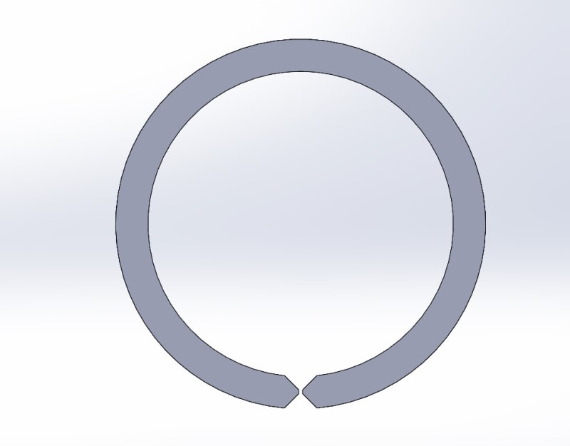
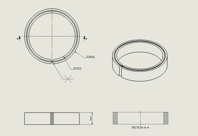
This is a photo of rolled of welded ring type flange. Alternatively, the dimension show there corresponds to 12'' SCH XXS which could be used as starting point for similar ring flange if for example I/D if this pipe is machined to suit.

Some Curious Gay, thank you again for your comments. Please find me response below:

a) I have read 2-14 and found this string of text in 2-14 a) Successful
service experience may be used as an alternative
to the flange rigidity rules for fluid services that are nonlethal
and nonflammable and designed within the temperature
range of −20°F (−29°C) to 366°F (186°C)
without exceeding design pressures of 150 psi
(1 035 kPa).

Does it mean that 2-14 is not mandatory?

b) I am curious if a piece of pipe can be used in this topic
c) agree on this
d) I think you are correct here.
 
r6155, sorry mate but I don't get what you need. This is the drawing of the ring flange. You can now imagine for an example a blind flange with slotted holes goes on top of that and swing bolt brackets welded to the ring flange. It is simple as that.
 
I don't need anything, you need.
Forget this design. Are you planning to build a layered vessel as outlined in ASME VIII-1?
See PART ULW
REQUIREMENTS FOR PRESSURE VESSELS FABRICATED BY LAYERED CONSTRUCTION.

Regards
 
mech8790, if using the rolled ring as shown I'd RT the weld seam even though Apx 2 does not seem to require it. Just good practice.

Given that, I'd guess the pipe section would be more economical. As I said before Code does not prohibit it.

Perhaps you saw this discussion of a similar design.

Regards,

Mike

The problem with sloppy work is that the supply FAR EXCEEDS the demand
 
Status
Not open for further replies.
Back
Top