Eng-Tips is the largest engineering community on the Internet

Intelligent Work Forums for Engineering Professionals

Flanged wheels ball bearing loads 1

Status
Not open for further replies.

Algirdas13

Mechanical
May 27, 2023
36
0
0
LT
Hi everyone,

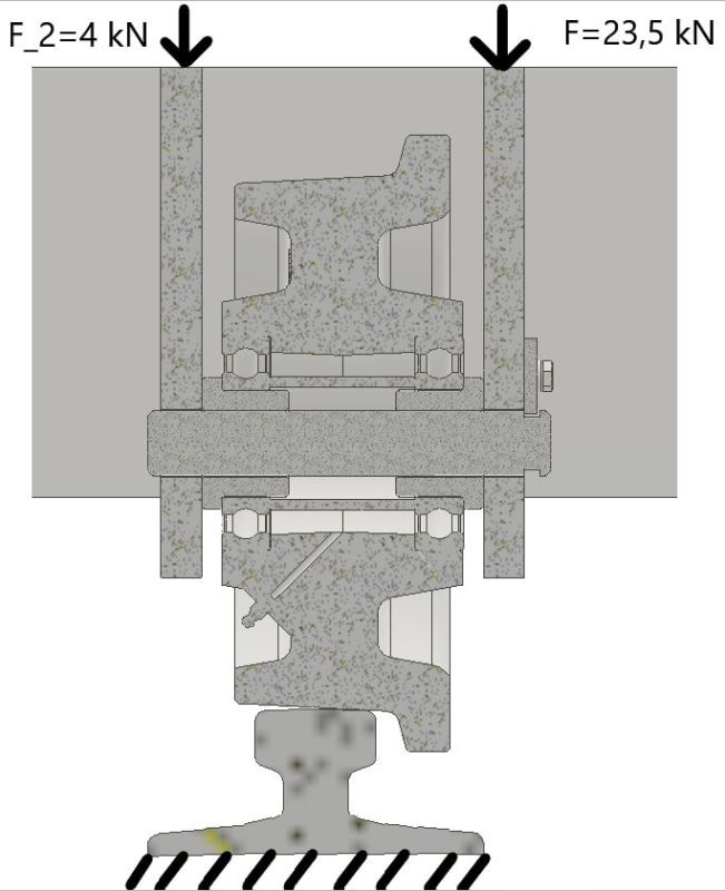
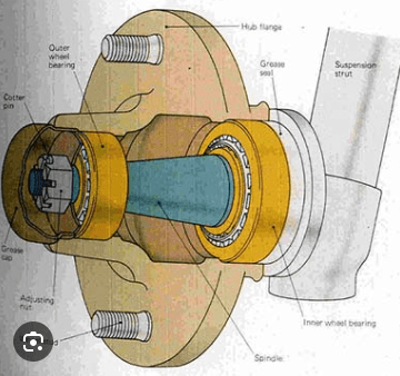
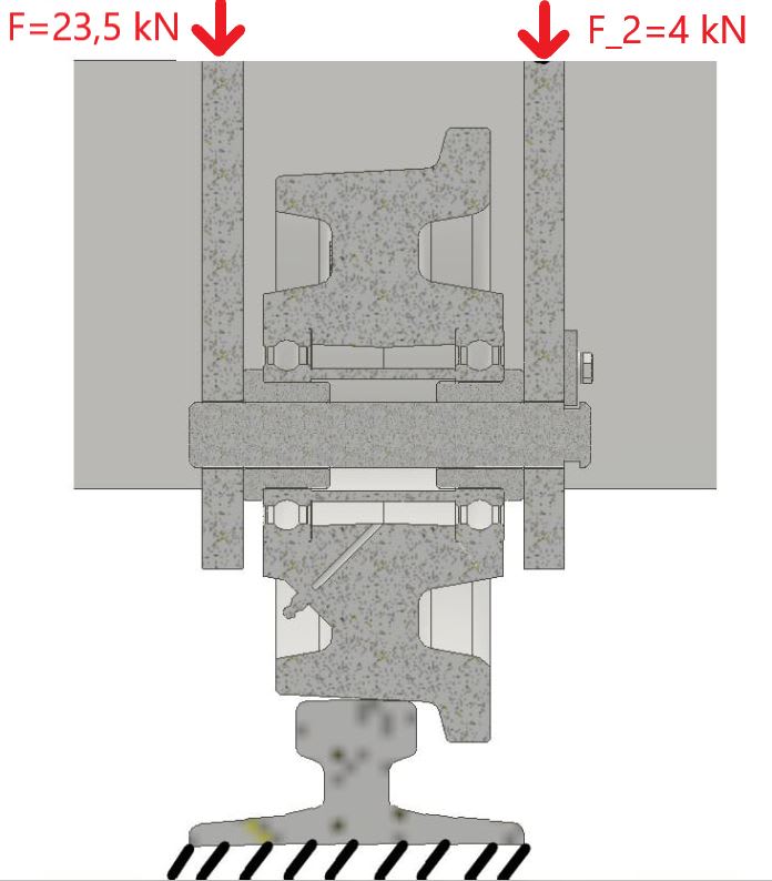
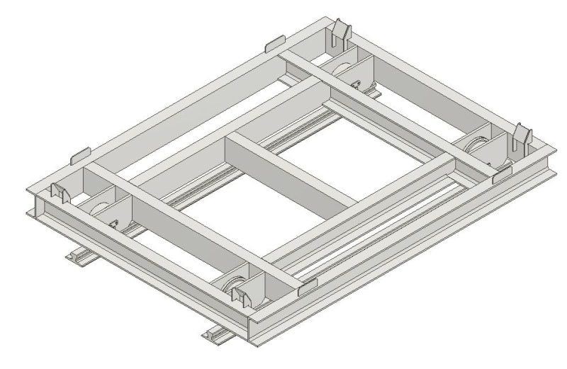
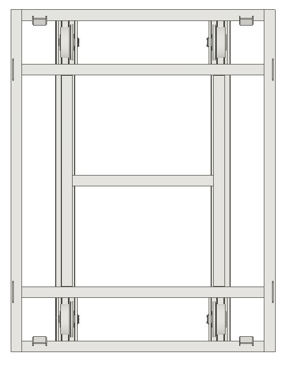
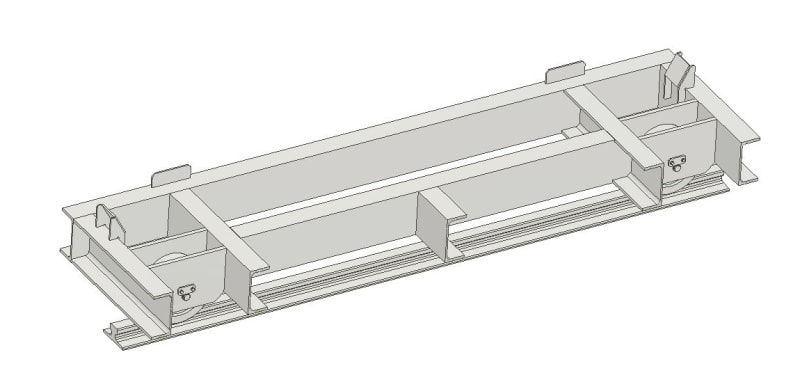
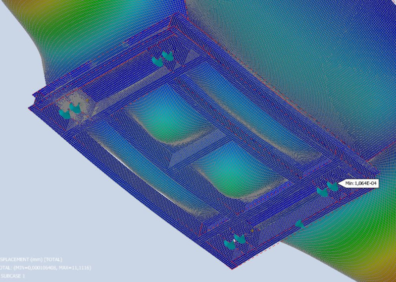
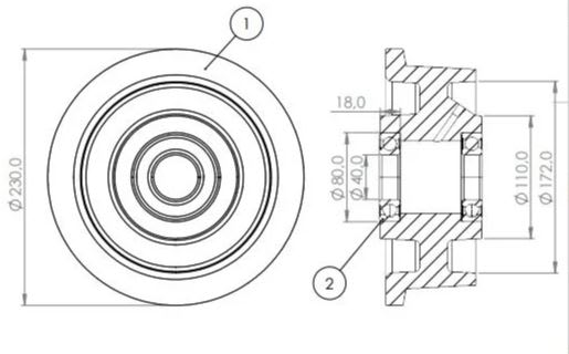
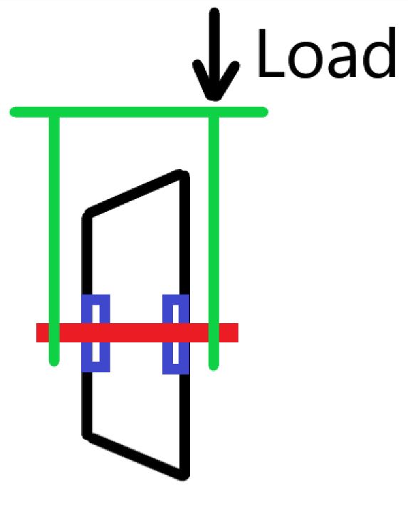
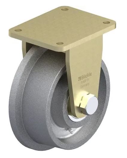
I'm planning to use fixed castor flanged wheels (1st picture bellow). The wheel itself has two bearings inside the wheel (2nd picture bellow). The rated load capacity for wheel is 3 tons. For example if I'm gonna load wheel with force that is not symmetrical in a view of wheel, does this mean that I cannot assume that wheel's capacity is 3 tons, but rather 1.5 tons (assuming that one bearing load capacity is 1.5 tons)? The load schemes are bellow.

I would be very grateful for any information.

1st_picture_yhg3bw.jpg


2nd_picture_rtxhvt.jpg


3rd_picture_bzmfut.jpg
 
Replies continue below

Recommended for you

Hello Stress Eng,

Please find the boundary conditions for the wheel bellow. The wheel's capacity declared by manufacturer is 30 kN. The loads F and F_2 are evaluated from the FEA of the frame.

BC_w2iyd1.jpg
 
Just a glance at the load capacity chart for a single row bearing of the same size suggests that bearing capacity is not the limiting factor.

The bracket and axle will transfer some of the load to the other side, in proportion to the stiffness of the components.

Assuming a load capacity of 1.5 tons will probably be conservative and safe.
 
Ask the manufacturer to make sure. If the load rating depended on how the load was applied to the base plate, that would have to be defined in the load rating and would make the rating almost meaningless. Load rating must apply to loading any where on the base plate. Sure the actual load on each bearing will vary in reality.
 
How do I say this nicely? I doubt your premise. According to your diagram above, the left side of the top plate is completely unsupported. I doubt it.

I'm guessing you actually have four casters in the system. There are two rails, right? And two casters on each rail, right? And those casters are all mounted on a common stiff frame, right? That's why I doubt your premise. To examine one caster without accounting for the loads on the whole system is misleading.

Can you show us a diagram of the complete frame and loading arrangement?

 
Yes, I was thinking the same thing that Jboggs articulated, that it would be virtually impossible to apply loads like that, at least there's no way of being able to know that without a complete illustration of the device, including the structural components and how and where the load(s) are being applied.

John R. Baker, P.E. (ret)
Irvine, CA
Siemens PLM:

The secret of life is not finding someone to live with
It's finding someone you can't live without
 
It's analogous to the wheel bearings in the front upright of a car, where the inner ball race takes most of the load in a typical design, and the outer one merely provides the toe/camber stiffness.
As such when we used to have taper roller bearings the inner one was maybe twice the size of the outer.
image_2024-08-14_083409893_akeho0.png


But that only works if the load is applied off centre, which given a wheel on a rail seems unlikely.

Cheers

Greg Locock


New here? Try reading these, they might help FAQ731-376
 
Hi everyone,

Thank you so much for taking your time on sharing ideas and insights! I'm very happy with the activity level.

I will try to explain more in detail regarding the situation. I'm trying to design a trolley that will be used on rails. On the trolley there will be placed a container that will contain the fly ashes. I did an FEA where I evaluated the trolley's frame and the contact with the container (separation contact with the friction steel-to-steel). For trolley's boundary conditions I used a pinned constrains on brackets holes, where the pins will be located. Because of the difference of stiffness in trolley's frame and the container's body, the the loads distribution is not equal-symmetrical on the trolley's brackets. This is where from the uneven loading on the bearings comes from. The values of the loading on bearing are used from the reaction forces from the FEA pinned connections.

Previously I made a mistake and showed forces wrongly. Please find those fixed bellow.

Here are couple more pictures of the whole system:

BC2_ewuimm.jpg


Trolley_1_ay7jgc.jpg


Trolley_2_ujuoqv.jpg


Trolley_3_hvogul.jpg


Trolley_4_korsow.jpg
 
Since you have an FEA model can you show the same section with the strains?

Unless the image is not scaled correctly I would have expected the loading ratio of 60% vs. 40%, maybe 70% vs. 30% rather than having 85% on the one side.
 
Just a couple of observations. Both the container and the supporting frame look symmetric, and the wheel tapers are going outwards from the centre. Disregarding build tolerances, you have four contact reaction points. The ash takes the full internal shape of the container? If so, and the ash was level, what are the reactions at the four contact points? Is the non-symmetric shape of the wheel cross section sufficient to cause significant difference in the two load paths (disregarding lub’n boss & non-symmetric outer radial surface profile)? What will have an influence is the reaction point at rail contact relative to the pin contact points with the wheel bracket.
 
Stress Eng, for the validation I don't use wheels' geometry. I only use reaction forces from brackets supports that I get from an FEA. This is because I assume that wheel's eccentricity wouldn't make a significant impact on loads distribution between ball bearings.

3DDave, please find couple pictures from the FEA. The final results shows distribution 78/22. I believe this is because the container's most stiff structural parts are on the edges of the container's. For this reason I assume that the most of the load are transferred through the corners which are much closer to one of the supports. I believe this shows that this cart has an poor design for such application and that the trolley's frame should be redesigned.

FEA1_ky96ay.jpg


FEA2_mobmql.jpg


FEA3_fkrhfq.jpg
 
Three points define a plane - chances are pretty high that three of your wheels will bear the majority of the load. Unless the fabrication is perfect, it will be difficult to get the load to share over all four casters.
 
I wanted to know how a statically determinant condition has become statically indeterminant.

It appears it has become so because the loading is forced to become indeterminant.
 
As an observation, if the length between the two pin to bracket contact points is 30mm, a vertical rail reaction load offset by 3mm to the centre will result in a 60/40 load split, as suggested by 3DDave.
 
Again - how do I say this nicely?

You are over-thinking this WAY TOO MUCH! First - if the actual loads on opposite sides of the wheel are truly unequal, you know that will result in angular displacement. The wheel axis will not remain horizontal. It will rotate about the rail contact point toward the heavier load. But we know it will remain horizontal, so the whole unequal loading thing is a false assumption.

Your FEA numbers and analysis may indicate an unequal loading on each end of the axle, but we know better. That's why I'm saying you're over-thinking it. The real world is telling you more than your equations. Believe me those two bearings are equally loaded. You need to get this simple one behind you and move on to more complex problems.
 
What are the boundary conditions imposed by all the green cones?

green_cones_ksxtdo.png


I'd guess they are not representative of what will happen in real life, and are skewing the FEA output.
 
Status
Not open for further replies.
Back
Top