Continue to Site

Eng-Tips is the largest engineering community on the Internet

Intelligent Work Forums for Engineering Professionals

  • Congratulations KootK on being selected by the Eng-Tips community for having the most helpful posts in the forums last week. Way to Go!

Flash Steam Recovery by Restriction Orifice 3

Status
Not open for further replies.

AzArsha

Industrial
Jul 19, 2017
10
We are now working on designing a Geothermal power plant. In a specific point condensate with 10 bar in 200 ton/h flow rate should be flashed to recover extra steam of 6 bar for using as motive steam in ejectors.
Based on our calculation, in such pressure changing, we can obtain about 3% (of 200 ton/h) steam.
Does anyone has similar experience on using a restriction orifice as flashing device and also a separator drum on downstream for extracting flash steam?
Please advise us on above specific method. Any alternative method can not be done by now. Its all matter of time.
 
Replies continue below

Recommended for you

Sorry, I've used a control valve to give the plants some flexibility.

You should check your calculations though, I think you should recover about 4% as steam.

Good luck,
Latexman

To a ChE, the glass is always full - 1/2 air and 1/2 water.
 
As the recovery with a RO could be a simple and quick solution, the system needs to be somewhat steady in flow, P & T, etc., for a consistent output. However, it may be difficult to meet the design requirement.
 
Dear Latexman
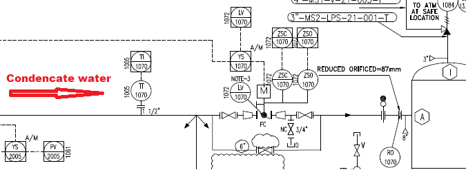
You right. Our 3% is calculated with a margin to being ensure about performance. But the main point is as you said, using control valve as a flash valve. Actually in upstream of restriction orifice, there is butterfly type control valve that regulates a level of some vessels.
In our first design, the control valve had such duty (flashing), but valve type, generated noise and erosion of valve pushed us to use a RO instead.
Do you think we are in a right path?
 
Dear mk3223
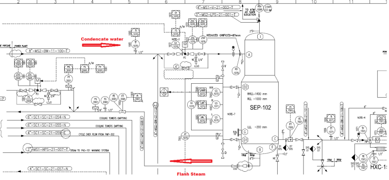
Please take a look to our P&ID attached and share with me what you think about.
flash_steam_g6sx2c.png
 
That's better than initially presented, but I worry when I see "Flash Steam" coming out of the bottom of a separator. That is highly unexpected, but I have not seen the internal details of your separator. I suspect an error on the P&ID, and the Flash Steam is going out nozzle "C".

How do you "ensure about performance" of the downstream flash steam design if you use 75% of the expected rate? I would understand using 75% of the expected rate in the economic justification of the project to balance any risk of below normal production levels, but not in the flash steam downstream design.

Good luck,
Latexman

To a ChE, the glass is always full - 1/2 air and 1/2 water.
 
OK. first, in separator there is a vertical pipe connected to nozzle B.
Maybe it was just a misunderstanding. Downstream required steam is about 3% and the rest will be vented.
Despite all of these details, Do you have any major comment on designed arrangement of valve and RO? Have you ever seen such arrangement before (for steam flashing purposes of-course)?
 
Ah, understood on both items. It may help to show that pipe in dashed (invisible) line, for better understanding. No, I have no major concern. It should work.

Good luck,
Latexman

To a ChE, the glass is always full - 1/2 air and 1/2 water.
 
Thanks for sharing the details.
For a typical condensate knock-out drum, the steam out is at the top of the vessel with an internal demister pad, which is to knock down excess condensate from the steam stream. And, the condensate is to flow out at the bottom of the vessel.

Your design is okay for your purpose and, as mentioned, the most of the low pressure flash steam is to be vented. IMO, some condensate is to be carried over to the flash steam, instead of recovering and recycling back to condensate steam. It could be a loss energy and $$ issues. To make sure the RO-1070 won't restrict the flow too much to impact level control through LV-1070.
 
If load is not constant two sets of valves & orifice for 1/3 and 2/3 flow respectively would work better.
 
Hi All,

You might very well need no orifice at all, it really all depends on what you have upstream (before condensate stream) and downstream (outlets of flash vessel).

It is important to understand well what happens upstream (the initial point of your problem was a stream of condensate. With upstream, I mean what is generating and how it is being generated that condensate - which I Assume is saturated - otherwise, the problem is not sufficiently defined). Also convenient to have a good understanding of downstream conditions and restrictions

But the main idea I want to stress is that there is no need to install a restriction (flow pressure drop) to create the flash steam. In fact, in many applications it is simply non desirable.

Example (I don't mean this is the case):

If you have 250 steam traps discharging condensate into a condensate line, with an overall steady result of a condensate stream of 200ton/h 10bar SAT, you can simply get that condensate stream into a big separator tank, and install a control valve on the top to deliver the flash steam (obviously also some means for discharging remaining condensate in the bottom). Simply control that valve based on downstream flash steam pressure (6bar) and you are done.

When the valve opens, it will create a depression in the vessel and flash steam will generated (100% efficiency as pointed bt Mr. Latexman). It is all about ensuring sufficient diameter in the separator to avoid condensate carryover with the flashing and sizing the valve correctly.

But really, no need to create any pressure drop before condensate enters the vessel to force flash steam generation (what on turn, if using a calibrated orifice, has the disadvantage of needing precise sizing of the orifice and resulting lack of flexibility).

Another story would be to use a flow restriction (i.e. orifice) to divert only part of that 200ton/h stream into the flash vessel.

I don't know if my explanation was a bit confusing....

BR;
RSpain

 
Dear Rspain
Condensate has been generated from or better to say separated from two phase fluid of Geothermal well and It is saturated, yes.
Downstream of separator there is set of ejectors that designed to consume steam as motive fluid in specific process conditions.
You right, at very primitive design of us, we considered a pressure control valve exactly downstream of separator. But ejector manufacturer ensured us there will be no need to such PCV. He guaranteed that the mechanical structure of designed ejector will secure all required conditions of pressure and flow.
But actually we are not so sure.
What's your idea about this?
 
Hi,

Difficult to be confident not knowing the P&I of this ejectors and the specifications that have been considered by manufacturer - but doesn't sound as sufficient convincing kind of statement... I would ask to the ejector manufacturer "What exactly do you need to be supplied to the ejector's motive inlet to guarantee desired operation". Depending on the answer to this, the design might change...

If manufacturer is counting on a supply of 6bar steam for the ejectors motive steam inlet, I think that the easier way forward is to get the condensate directly into the separator (with no previous flow restriction, ensure a controlled as low as possible condensate level inside the separator by adequate condensate removal through lower separator outlet (level-controlled discharge valve, steam trap, condensate pump, etc.) and installing a PRV on a top outlet of the separator.

Difficult to know without more data...

PS: sorry, when I say lower&top, I'm not looking at your actual separator, just thinking in a hypothetical P&I-like separator

PS2: can you link to a bit bigger and higher resolution P&I of your process?

BR,
 
This is not steam condensate. This is separated geothermal water.

Flashing geothermal water after the first stage separation to generate more, lower pressure, steam is very common. Usually most of the LP steam is used in the steam turbine rather than for the ejectors.

Control valves are used to flash the water. They would be controlling the water level in the first stage separator.

If you use a orifice this will be either be too small and the water will back up and have to flow elsewhere or too larger and you will loose some HP steam in the LP.

The early days of geothermal fixed orifices or manual valves were used and some HP steam was wasted. These days control valves are used.
 
Dear KeviNZ
Thank you.
Right, this is a geothermal plant. As I explained in past posts, our very first design was based on flashing on a control valve. But we did not sure about either flashing on a butterfly valve or even huge erosion occurring in that.
Flashing in butterfly I think little weird. We think flashing maybe better to be happened in something like a globe valve. But because of some matters we couldn't able to replace it. Our solution is, as depicted in above P&ID, using a control valve for flow control of condensate consequently level of first stage separator and an orifice plate for flashing simultaneously.
Beside all of above, what do you think? Do you have any better solution or suggestion?
 
AzAsrha

We have used ball sector or globe type control valves. Even made our own or used a modified gate valve. The valves are always in use so no need for a seal. This gives more options.

You can use an under sized orifice plate plus a parallel control valve for trimming.
 
Status
Not open for further replies.

Part and Inventory Search

Sponsor