Continue to Site

Eng-Tips is the largest engineering community on the Internet

Intelligent Work Forums for Engineering Professionals

  • Congratulations MintJulep on being selected by the Eng-Tips community for having the most helpful posts in the forums last week. Way to Go!

Flexible Diaphragm Analysis

Status
Not open for further replies.

SliceCity

Structural
Dec 22, 2022
16
Hello All,

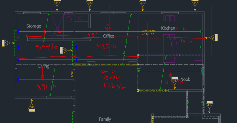
I am working on the design of a second story addition for a residential house. I am trying to carry the second story shear wall load in the first story diaphragm and shear walls. Due to the existing condition constraint, I cannot place a shear wall directly under the second story shear wall to transfer the load. I currently have the second story shear wall supported by a beam with collectors. I am hoping for a sanity check to confirm that I am analyzing this correctly.


I am assuming that 40% of the second story shear wall will transfer through the diaphragm be resisted by the north face shear walls. The remaining 60% of the second story shear walls will be supported by the two west faced shear walls at the living area and the nook. Since I have discontinuity between the two west faced shear wall, due to the opening above, I am thinking that the way I distributed the loads is not correct. I am thinking that along the length where I have a discontinuous diaphragm, all the load will transfer to the north face shear wall. I would divide the shear load by the total length (say 50ft) 4500/50= 90lb/ft then assuming the length of the discontinuous diagram is about 16.5ft i would apply 1500ft along the north shear walls + 40% of the remaining load. I would then apply 60% of the remaining load along the south face shear walls.

Please see attached.

 
 https://files.engineering.com/getfile.aspx?folder=c691261f-3e61-44a9-a01e-3bf383824144&file=Flexible_Dia_Analysis_Snipit.PNG
Replies continue below

Recommended for you

Okay so this discontinuity can really affect the stiffness of the shear walls above. But if your using flexible diaphragm analysis then you 'might not need to worry about that'.

Where are you coming up with these percentages, they should just be based on tributary width for flexible approach.

I don't see the issue in just taking the actual shear wall reaction from the SW above and applying it as a point load on the diaphragm below (transfer diaphragm).
Then you can see how much load should be going into those shearwalls on the plan south side.

Going back to my original point, the upper roof diaphragm may want to act more like a three-sided diaphragm dude to the increased relative flexibility of the discontinued shear wall support.

Have you studied Malone's book on diaphragms? Your lower level diaphragm here could be analyzed by braking it into (3) or more rectangular diaphragm regions.

And since you appear to be on the west coast, what about Seismic? Don't forget that this discontinuity raises additional requirements.
 
Thanks for the fast reply @driftLimiter! I am getting the 60% & 40% distributions based on the the relative distance from the point load from the SW above to the North and South SW below. My issue that at the location where the SW above is connected to the diaphragm at only one side, all the load along that length will want to transfer to the north side and and then the remaining load will transfer between the south SWs. I do have the storage & living, office, and kitchen and Nook areas diving into sperate diaphragms. Please see attached.
 
 https://files.engineering.com/getfile.aspx?folder=cd7b1ba3-de0d-4422-a2aa-6d5a9c0a58b8&file=Flexible_Dia_Analysis_Snipit_#2.PNG
SliceCity said:
My issue that at the location where the SW above is connected to the diaphragm at only one side, all the load along that length will want to transfer to the north side

Your image didn't load correctly, perhaps that would help.

I'm not following this. For your discontinuous shear walls I would expect you have a large beam underneath it is tied to an adjacent member (on its left and right) that will act as a drag strut.

 
Your pictures are still not loading for me. Still not understanding what your concern is here.
 
Flexible_Dia_Analysis_Snipit_2_z8xwus.png


Lets try it this way. Sorry
 
Okay so I believe what you're saying (please correct me if wrong) is that your not sure how the 1485# component of the upper level shearwall load transfers.

I'm not sure that is how I would think of the loading. I would assume that all of the shear from the discontinuous shear wall ends up in your collectors. Your rendition of the loading might be more akin to looking at the office/storage/kitchen floor diaphragm as a 3-sided one.

But I am saying you have the Storage/living room diaphragm, and the kitchen/nook diaphragm that are responsible for resolving the discontinued shear wall loads.

Hope that helps.
 
I can't figure out quite what you're trying to do, even with that image. You don't seem to have shear walls below or above marked? Even so, I'll through something against the wall and see if it sticks:

The way I prefer to do this, for shear, is to look at the transfer diaphragm as a series of single span beams with reactions at each shear wall below. This is the easiest way to divide up the loads based on tributary area when you're considering point loads. This will give you shear in the diaphragm and transfer loads pretty easily.

Of course, don't forget about the vertical reactions at each end - that also has to be resolved.
 
See what you mean. That is more in line with my original approach. 40% of the shear load from the SW above is resisted by the north SW along D1, D2, & D3 and 60% of the shear load is resisted by the south SWs in D1 & D2. The load in D1 and D2 is distributed per the length of each diaphragm.

I dont need to make any considerations when designing the D3 Diaphragm? No load is transfer through it?
 
D3 is responsible for wall loading of the first level in the storage - office - kitchen region.

Think of D3 as supported by shearwalls on the north, and by the Drag strut at it's south.
 
Perfect! That makes sense to me! Thank you very much!
 
Okay you've got your answer now I want mine lol. Have you considered the penalties for this configuration on your seismic loading?
 
Status
Not open for further replies.

Part and Inventory Search

Sponsor