Continue to Site

Eng-Tips is the largest engineering community on the Internet

Intelligent Work Forums for Engineering Professionals

  • Congratulations KootK on being selected by the Eng-Tips community for having the most helpful posts in the forums last week. Way to Go!

Flexible Tank Floor Affecting Agitator's Installation 3

Status
Not open for further replies.

ReliaEng2008

Mechanical
Mar 5, 2021
22
At my site there is a new API 650 atmospheric storage tank (29' ID, 40' max liquid height). Steady bearing legs for an agitator need to be installed inside this tank (I don't know much about rotating equipment, so I don't know how these bearing legs work). The personnel working on the installation of the agitator noticed that the tank floor is not flat, and it’s very flexible. There is a considerable amount of bowing/deflection of the tank floor plates, noticed by just standing on them (like if you would be standing on the hood of a car and it would be popping in and out). The tank floor is made of stainless steel and it is 3/16” thick.

The bowing/deflection is affecting the installation of the agitator; it will make it hard to align the bearing to the shaft. The bowing/deflection could also change when the tank is full, potentially forcing the shaft to deflect or exceed its deflection limit, and causing bearing failure and/or even shaft damage.

A solution suggested by the agitator's vendor was to drill holes on the tank floor, and fasten the tank floor to the concrete foundation using bolts, and then weld around everything so there are no leaks through the tank floor. It is hard to explain this solution using only written communication. The vendor showed us a picture of this work-around done in another tank from another site, but I cannot post it here.

I would prefer not to drill through a brand new tank floor. Does anyone have any suggestions or experience with something similar? I thought that maybe if we add water to this tank up to the max height for a few days, and drain it, the weight of the water would stabilize the tank floor. But I think that might not happen also. This tank has been filled with water in the past during hydrotest; and I doubt that filling the tank with water to the max height will result in enough force to plastically deform the tank floor and make it conform to its foundation.

If we do end up fastening the tank floor to the concrete foundation using bolts, a new hydrotest would be required, right?
 
Replies continue below

Recommended for you

Maybe add a heavy round plate in the center of the bottom, just lapped onto the bottom?
 
78379077973098794873897858943078579340780_pe1uar.jpg


I believe that you have been sold the wrong type of agitator .. You may want to consider a much more commonly used type

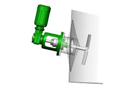
There is a long successful record in the use of a "side entry agitator" as shown here.... They have been in use for decades, They mount on shell manways


Some large tanks (such as yours) may require two or three .... A tank that is 29 ft diameter is very big for a single internal agitator

It appears that there was little or no consideration of agitator installation at the time of tank specification.

Is there a reason why you cannot use a top mounted agitator supported by a "bridge" ?

You seem to be the newbie at the tail end of the problem .... Classic MBA "dump the problem" management technique ....

Can you show us any drawings or sketches of the device/method you want to use to support the device within the tank ?

Will your MBA boss allow you to show us tank drawings ?

Is the agitator new or have you been told to re-use an old unit they found in the boneyard

Good luck

MJCronin
Sr. Process Engineer
 

- Do you have survey data of the bottom plate before and after hydrotest?
- Do you know the proposed dead load for the bearing leg ?


- Can you do a simple test , if the load is around wt of a person, when you stand do you feel the plate touches the RC slab? Just my feeling , the bottom plate 3/16'' is very flexible and the wt of agitator on the bearing leg will justify a stable bottom.

My opinions only!!
 
So is the motor on the outside of the tank and you have a long shaft and bearing for the mixer?

Alternative is to create a strong frame and mount it either from the walls or those locations where the floor is well fixed to the floor.

Cutting holes and then welding a stainless steel floor doesn't sound like a great plan.

A few more details or sketches would help.

Remember - More details = better answers
Also: If you get a response it's polite to respond to it.
 
The agitator systems I've worked with (usually in asphalt service) have a motor and vertical shaft that are supported by a structural bridge across the top of the tank with tall paddles and shell baffles. The lower end of the shaft is restrained from horizontal movement with a bearing sleeve that is on the floor. Because the thin tank floor can deform under the weight of the product, the bearing sleeve needs to be tall enough to accommodate any deformation in the floor plate. If the bearing sleeve is not tall enough, is it possible push the bottom plate down with a thick round plate seal welded to the tank bottom like a column bearing plate? Perhaps a 2" thick plate 48" in diameter would do the trick? Anchoring the tank to the foundation in one discrete location is not shown in API 650 and may bring trouble for a range of reasons, including unanticipated shear from unbalanced friction from thermal expansion, wind and seismic; as well as corrosion and leakage.
 
MJCronin said:
I believe that you have been sold the wrong type of agitator .. You may want to consider a much more commonly used type
I agree that the design of this agitator could have been much better. And yes, the tank was constructed by a tank manufacturer with no knowledge that an agitator would be installed on this tank later. That's not their fault, they just did not have the information and the design was approved. At this point in the project, there isn't much I can change besides finding a way to stabilize the tank floor and go ahead with the steady bearing installation.

HTURKAK said:
- Do you have survey data of the bottom plate before and after hydrotest?

What survey data specifically are you referring to? I don't know the details of the load yet. I have a meeting today to get the details


LittleInch said:
Alternative is to create a strong frame and mount it either from the walls or those locations where the floor is well fixed to the floor.
Yes, that is a good option.
 
Could you post more detailed information about the specific type of agitator that you are forced to use ?

How are the geared topworks/motor supported ?.... Is it supported from the tank roof or from a fabricated steel bridge ?

What is the vendor's proposed maintenance scheme to remove/replace and decouple the shaft ?

Can you post the agitator make and model number ? .... or will your boss prevent you from doing this ....

How about the vendors recommended bottom support scheme ? ... What details has he given you ?

Is he recommending a three legged frame with a little bit of flexibility or something else ?

Give us a little more to work with here ....

Some good information on Bottom Steady Bearing designs can be found here:


MJCronin
Sr. Process Engineer
 

Internal bottom elevation measurements are required before and after hydrostatic testing,and recorded . In order to understand the amount of buckling of bottom plates and how much fixed after hydrotest these records are necessary..
 
Page 16 of the attached MIXMOR installation guideline recommends a REMOVABLE bottom steady bearing with three flexible legs.

The bottom of the mixer shaft must be located some distance from the tank bottom and the design must allow for axial expansion of the shaft as well as periodic replacement of the lower bearings ....


In my opinion, some thought must be given to your agitator maintenance requirements before you can arrive at a final design ...

If we assume that you have a long thick and heavy shaft ( 3 to 4 inch .diameter ?) then we can also assume that the shaft will have a mid-coupling for installation and possible removal. When the coupling is disengaged, the shaft WILL DROP SLIGHTLY to allow disengagement and disassembly. That drop must be allowed for in the design of the bottom steady bearing

... and if you have a contract maintenance team like most plants, they will not care if the shaft drops to puncture the tank bottom (Ooops, so sorry !) I have seen this happen

Therefore, I suggest that you design a circular steel pad that the bottom steady bearing can be attached to THAT WILL SUSTAIN A SHAFT DROP ... Perhaps a 3/8 or 1/2 inch plate.

But, then again, you seem to have lost interest in this thread and have gone off to do other things ...

(Your tank, of course, must be drained, inerted and a maintenance team must enter when the agitator starts vibrating and the bearing require eventual replacement)

Maintenance people love these things ...


MJCronin
Sr. Process Engineer
 
Drill a hole at bottom away from shaft. Push cement slurry through it & Close the hole by welding patch, This will avoid deflection of bottom when full.
 
I design agitators for a living. Having both a flexible floor for the steady bearing and flexible nozzle to support the agitator is among the riskiest installation conditions I can imagine.

29'x40' high is not bad proportions for blending/homogenizing low viscosity products. It could be challenging geometry in which to suspend solids but since you have a steady bearing I assume you're working with refined product.

First, the steady bearing will only see load when the tank is at least partly full. Your operational controls need to assure this. So there will always be fluid pressure on the tank floor when the steady bearing is supporting load.

So with fluid pressure present, the oil-canning of the tank floor should stop. But unfortunately, it may also move the center of the steady bearing. A short, wide steady bearing tripod is favorable. Walking on the not-flat floor and adding tank liquid both have excellent leverage to make the floor move. But to your point, it will likely deflect back when it's empty.

It would be interesting to align the steady bearing somehow when the tank is being hydro tested with the mixer in place. Optical alignment tools could work, assuming the top of the water does not prove to be an issue.

How much lateral force does the steady bearing produce? The steady bearing lateral forces probably don't have much leverage to make the floor. In theory the steady bearing forces may have little effect on the floor.

Has the agitator manufacturer provided nozzle loads and deflection limits? And has the tank vendor re-analyzed the tank nozzle to ensure it will not be over-stress, deflect excessively, or shift the mixers critical speed?

Another random thought: can you inject grout or epoxy compound under the center of the tank floor, to support the natural waviness of the floor and ensure you can the steady bearing from moving around when the tank is full?

Any chance you can convert the steady bearing to a limit ring / bump ring? That should be far easier to maintain.

Sorry my answer is mostly questions. There are many variables here.
 
I think I'd modify the center of the foundation to include a concrete section 8 feet in diameter, fully and properly supported so as to be tied to the foundation under the shell. Then I'd place a 3/4" round plate 6 feet in diameter in the center of the tank to which the regular bottom plates are lapped onto and welded to, similar to annular ring plates. This should eliminate the flexibility issue and provide a solid base for the bearing regardless of liquid loading.
 
"As is typical of Third World engineers." - location of the OP says Texas.....

Remember - More details = better answers
Also: If you get a response it's polite to respond to it.
 
Thanks for everyone who commented. I no longer need assistance with this issue. We are considering that the weight of the process will stabilize the tank bottom and added protection so the agitator cannot be operated when the tank is at a low level. This is a very low impact operation and we can consider design modifications in the future if we need to.

MJCronin said:
As is typical of Third World engineers. the original poster has gotten what he wants and has dropped the thread

No need for xenophobic rhetoric here, Mr. MJCronin.
 
Xenophobia is in the eye of the beholder, ..... Mr. Reliable

I did, however, get you to finally respond with your reasonable and well thought out solution ... Thank You !!!

This thread is enriched and completed with your response ....

MJCronin
Sr. Process Engineer
 

Internet country domain does not mean the location of the OP is the same country.. but i did not get exactly ..Is the final solution DO NOTHING ???
 
The problem though would seem to remain - i.e. the bottom bearing / alignment will change as the tank fills up and the floor flexes.

You can only align the agitator when the tank is empty I assume so operating once it is full of fluid will change the bearing orientation surely?

And don't worry too much about MJC - he is in his own words old, grumpy and prone to outbursts and at least you don't have an MBA - he really doesn't like people with MBA's....

Remember - More details = better answers
Also: If you get a response it's polite to respond to it.
 
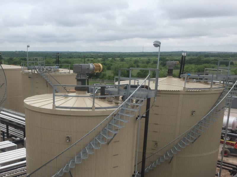
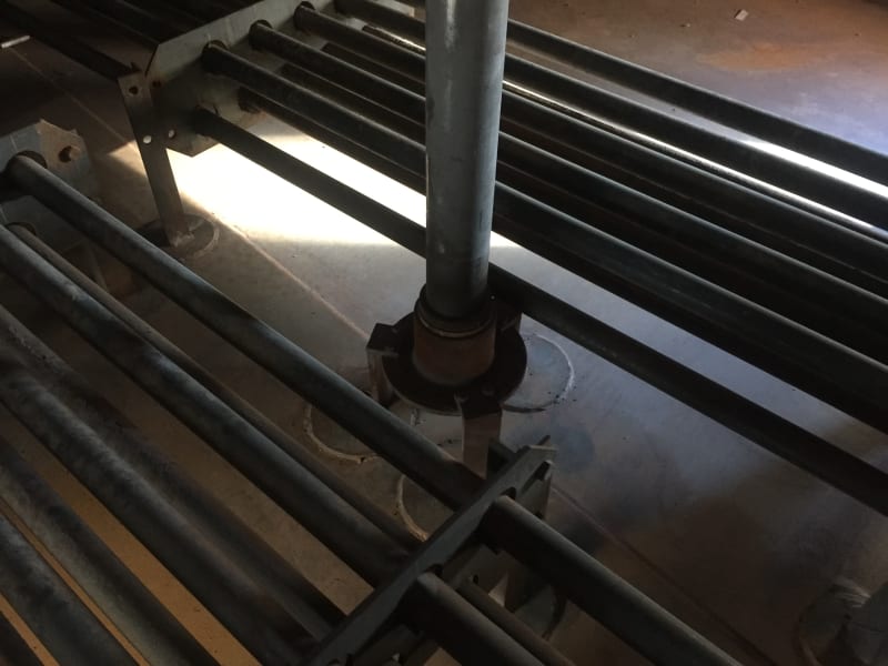
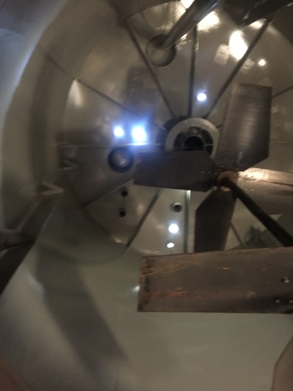
Three images from a similar install for asphalt. We use a heavy weight such as a W beam or section of railroad steel to hold the floor deflection down till the steady bearing is installed if needed. The product will hold it down in service and when the mixer is running. Note that the roof must have internal or external rafters to support mixer uplift forces and weight...a vertical mixer shouldn't just be added to the roof of a typical API650 cone roof tank (that at smaller diameters won't even have rafters). The 40' height is a bit extreme...we try to stay at 34' to keep the mixer shaft from being humongous.

IMG_8271_-_Copy_okxfhh.jpg

IMG_8716_oicfz7.jpg

IMG_8717_fvfvbz.jpg
 
Status
Not open for further replies.

Part and Inventory Search

Sponsor