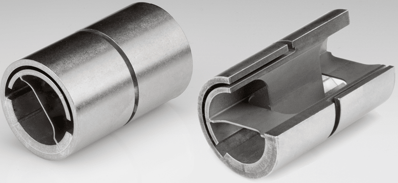
I am attempting to analyze the stress and torsional spring rate of rotational flexure bearings, such as shown below.
For those not familiar, these friction-less bearings allow only rotational motion while providing some torsional spring rate. They do this by bending a set of thin cross-section springs which are configured perpendicular to each other.
Initially I assumed I could analyze each arm as a cantilevered beam, with a force applied at the end. I found good information about analysis for large deflection angles, and planned to use that.
However, a few things I have seen indicate that the flexure arms have a uniform stress distribution, which I interpret to mean that it would be a moment-loading case to the cantilevered beam rather than force loading at the end of the beam.
I assume the fact that the arms are perpendicular makes the load case of each arm more complex, because they impart forces on each other.
If I can analyze as a cantilevered beam, I am trying to understand what loading case it would have. I cannot reason it out and it is driving me crazy. I'm making a free body diagram to try to understand it, but would appreciate if someone could point me in the right direction while I'm beating my head against the wall and confusing myself worse.
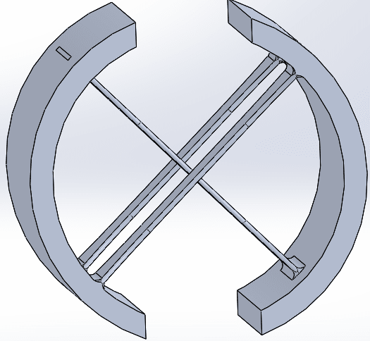
The 2nd image below shows just the core to help with understanding of how it works. Imagine one of the circular sections fixed and the other being deflected.


