Eng_Struct
Structural
Hi Group,
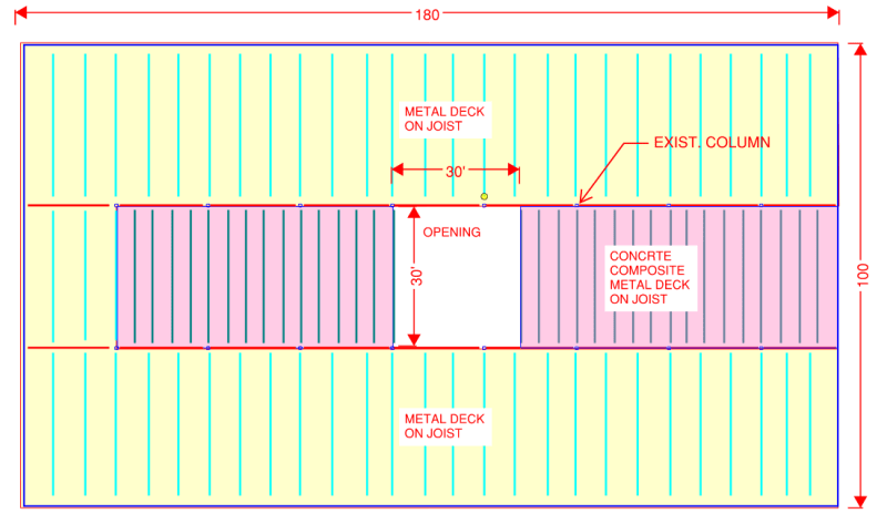
I have an existing two story building (180 ft x 100 ft in plan) and client wants to cut a large opening through the middle of the first floor. The proposed opening size is roughly 30 ft x 30 ft. The existing second floor is 4.5" concrete composite metal deck on joists. As part of the opening we will be removing some joists for their entire length.
In my mind the opening is not going to effect the gravity load path but it will impact the lateral load path due to the discontunity in the floor that is currently acting as a diaphragm. I wanted to get some advice as to how to analyze the floor to capture the effect due to the discountinuty.
I am thinking I will have to provide perimeter beams around the opening and possibly with moment connections to the columns. Depending on the direction of lateral load, the perimeter beams perpendicular to the load will have to deflect around weak axis and take the load to the column and push the column in the direction of the load. The beams parallel to the load between the columns will provide frame action and will resist the load as they now become part of lateral load resisting system. The columns will need to be reinforced and the load path to the beam perpendicular to the load and to new "moment frame" will need to be defined clearly.
Beside relaying on the moment frame, I am not sure how else I can carry the load around the opening through the deck and/or existing joists. Note that the existing lateral load resisting system is masonry wall around the parameter.
My main questions is what is the best way to analyze this condition and what kind of things I should be checking in the analysis model. What I have currently planned is:
1. build a model with floor framing and assign floor deck using plate elements in the analysis program
2. check the forces in the framing members around the opening i.e., axial force, bending, etc.
3. currently i have joists for the framing system and I do not believe the joists will behave as intended if loaded in compression.
4. check story displacement to understand the impact of the opening
5. Do trial and error to come up with what is required however knowing the answer I need to get to before I start on this will help. As of now I do not know what the answer is.
Thanks