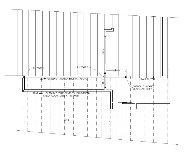
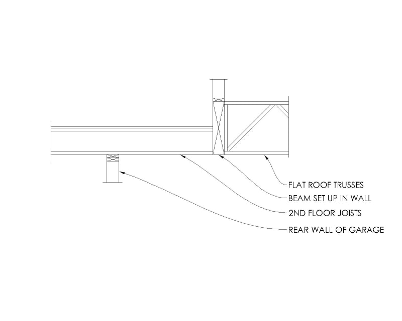
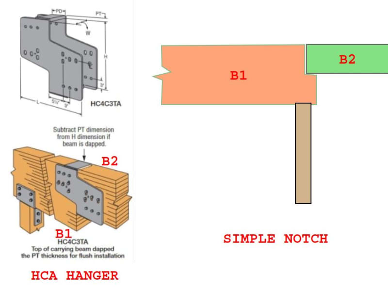
I am working on a residential project with an interesting framing layout. What I have is a second floor that does not align with the main floor wall below. I have a large glulam beam that will be "set up" so that it does not drop down below the bottom of the floor joists. I have floor joists for the second floor that hang into the beam on one side. The other side of the beam has a flat patio roof that hangs into it. See the framing layout below.
I am having some issues with two items. The first issue is that the floor joists span approximately 21' feet to the garage bearing wall and then they go an additional 4' to get to the glulam beam. My calculation shows that if the floor joists hang into the glulam beam they will each put a rather large uplift load into the beam. Should I not detail the joists to hang into the beam, but cantilever instead? Should I note that the joists should break at the bearing wall so they aren't continuous joists? My worry with both of these ideas is that I am 100% that any detail or note I put on the plans will not be done correctly. The framers will hang the joists to the beam. If they do that, will that be a major problem later on? Will the floor joists explode out of the hanger and pull the sheathing up? Will nothing happen?
The other item I'm worried about is very similar. If I calculate the large glulam beam to bear in 3 locations then I have a massive uplift at Support 3. I considered designing the beam to cantilever past Support 2 and put a note on the plans telling the framer to NOT bear the beam at Support 3. Again, I am confident that the framers will bear the beam at Support 3. I have an uplift force of 7,000 lbs. in that location if I design the beam to bear there. What will happen if they do indeed bear the beam at Support 3? Will the connection "fail" and then it ends up going back to my cantilever design? Will it pull the floor sheathing and wall up with it?
My calculations show these large uplifts for the floor joists and the beam. What will actually happen in real life if the framers build it how I suspect they will? Would appreciate anyone's experience/knowledge on this topic. Thanks!


