Eng-Tips is the largest engineering community on the Internet

Intelligent Work Forums for Engineering Professionals

  • Congratulations waross on being selected by the Tek-Tips community for having the most helpful posts in the forums last week. Way to Go!

flow and DP for a control valve

Status
Not open for further replies.

unclebensrice

Petroleum
Oct 1, 2010
44
0
0
GB
Dear all,

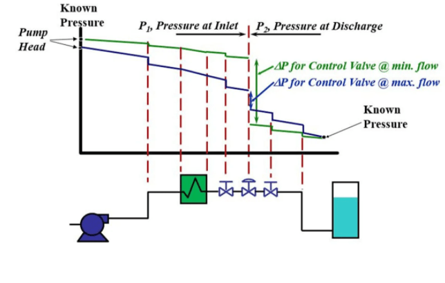
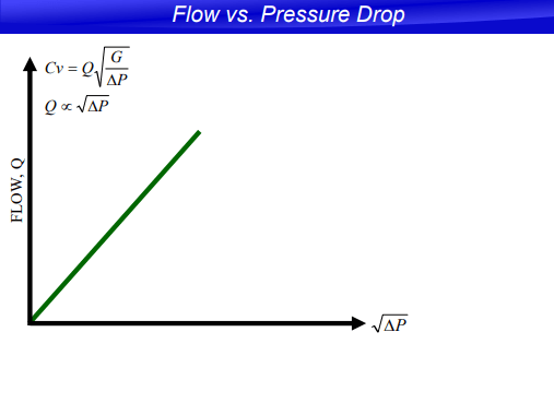
how do you reconcile pic1 with pic2. Pic1 shows that at low flow (minimum flow) the DP across the control valve is high whereas in pic2 low flow is proportional to low DP across the control. can anyone please dispense my confusion over this ? thanks.
pic1_n26aao.png
pic2_gco2il.png
 
Replies continue below

Recommended for you

Pic 1 shows what happens during operation, I.e. what happens as the control valve opens and closes.

Pic 2 shows what happens at a fixed control valve position.

So in your second pic the line at low flow, with valve closed more will be at a lower angle to the horizontal than the line at high flow when the line will be at a higher angle.[pre][/pre]

Remember - More details = better answers
Also: If you get a response it's polite to respond to it.
 
Thank you littleinch as always you're the first to reply with logical answers which I appreciate. Can you elaborate on angle to horizontal?

Thank you trueblood yes so the slope is the Cv which is fixed in this pic. But if control valves have variable Cv then why do we calculate one value of Cv during sizing. Thanks.
 
What I mean is that in pic 2 this is at say 50% open with an angle of 45 degress to the X axis

At say 25% open the angle is closer to 15 degrees to the X axis, but at say 70% open the angle of the line in closer to 65 degrees to the X axis.

Normally you calculate more than one CV for a control valve, usually min flow, max flow and "normal" flow and aim to keep the valve in the 25-75% open range to deal with the variance in flow or pressure. Sometimes people quote a 100% open CV for use in max flow, but for good control you need to aim in the 25-75% open range.

If you only have one case of flow and pressure then you might as well install an orifice / RO plate instead....

The whole purpose of control valves is to control on something (flow, pressure, temperature, level) and vary its CV between certain values that you anticipate in your process design work.

Remember - More details = better answers
Also: If you get a response it's polite to respond to it.
 
thanks littleinch

anyways im gonna be collecting the process data but what i dont understand is do i collect the desired flow rates and corresponding pressures from pump curve or actual flow rates and their corresponding pressures form the field? because i have seen some data sheets where the difference between min and max flow rates is so large and ridiculous that it beats the whole purpose of control. also how do i collect p2 pressure (outlet pressure) if im still designing the control valve ? thank you sir.
 
Status
Not open for further replies.
Back
Top